Striking mechanism for a watch or a music box

a technology of a music box and a striking mechanism, which is applied in the direction of mechanical time indication, sound producing devices, instruments, etc., can solve the problems of difficult control of the mechanical impact between the hammer and the gong of a conventional striking mechanism, the vibration mode of almost all the gongs is activated by mechanical shock, and the optimization of acoustic efficiency is greatly limited. , to achieve the effect of reducing noise, reducing vibration, and maximizing energy transfer

Active Publication Date: 2012-06-14
MONTRES BREGUET
View PDF6 Cites 17 Cited by
  • Summary
  • Abstract
  • Description
  • Claims
  • Application Information

AI Technical Summary

Benefits of technology

[0016]Advantageously, it is possible to obtain magnetic self-regulation of the rotational velocity of the striking mechanism. It is also possible to provide the striking mechanism with shorter gongs than those used for a conventional striking mechanism. With this type of activation wheel fitted with a certain number of permanent magnets, it is no longer necessary to activate said gong using a conventional hammer. Moreover, any spurious noise linked to mechanical shock, and multiple impulses and interference therefrom on the gong vibration, are also eliminated. Several magnetic wheels may also activate the gong in different selected vibration modes according to the different rotational velocity of each wheel and the number of micro-magnets comprised in each wheel. Magnets of alternate polarity may also be placed on the wheel to maximise the transfer of energy to the gong.
[0017]Advantageously, the gong may be fitted with one or more magnets, which have the same polarity as the magnets of the wheel, when they are opposite the magnets of the gong. In these conditions, the gong magnets are attracted by those of the rotating wheel. During rotation of the wheel, a force attracting the gong magnets is periodically generated. In this case, if the gong comes into contact with the wheel, the gong can be surface treated to remove noise during contact with the wheel.

Problems solved by technology

The mechanical impact between the hammer and the gong of a conventional striking mechanism is difficult to control.
The same is true for optimization of acoustic efficiency, which is greatly limited within the audible frequency range, particularly within the range of frequencies between 1 kHz and 4 kHz, but also between 4 kHz and 20 kHz.
Likewise, the mechanical shock activates almost all of the gong vibration modes, but without allowing any selection of the activated modes.
The duration of impact of the hammer against the gong generally cannot be increased by altering the geometry, inertia and material of the parts involved, without also causing a marked decrease in the impact energy.
Due to the internal damping and acoustic radiation, the sound cannot be extended without repeating the mechanical shocks.
Further, mechanical shocks, particularly the impacts of the hammer against the gong, may lead to spurious noise, especially in the case of double impact, and cause wear of the gong, which constitute drawbacks.
As mentioned hereinbefore, any mechanical impact of the hammer against the bell may also cause spurious noise, which is a drawback.
One drawback of this type of electroacoustic vibrator is that an electrical control device is required to power the coil in order to vibrate said membrane, which requires considerable electric power consumption.
One drawback of this generator is that the coil has to be powered with an alternating current to activate the vibration of said pin and the resonance of the watch crystal, which requires significant electric power consumption.
As in the preceding documents, the electro-magnet has to be powered by an alternating current in order to vibrate the vibrating strip, using significant electrical power, which is a drawback.

Method used


Image

  • Striking mechanism for a watch or a music box
  • Striking mechanism for a watch or a music box
  • Striking mechanism for a watch or a music box

Examples


Embodiment Construction

[0023]In the following description, all the conventional parts of the striking mechanism for a watch or possibly a music box, which are well known in this technical field, will be only briefly described.

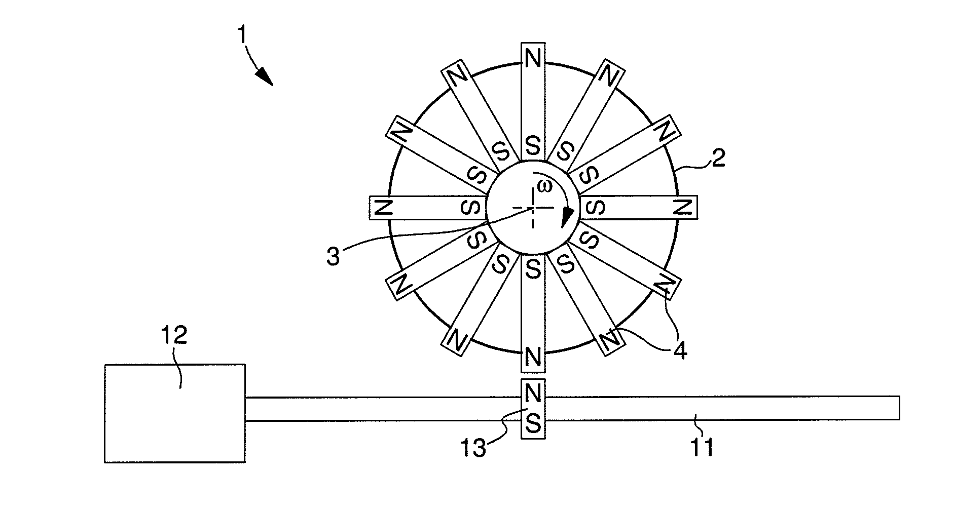
[0024]FIG. 1 shows a simplified view of a striking mechanism 1 notably for a watch. The striking mechanism first of all includes a gong 11, which is connected, for example, at one end thereof to a gong-carrier 12, whereas the other end is free to move. The gong-carrier may preferably be secured to a plate (not shown) of a watch movement, but it could also be secured to an inner part of the watch case, such as the middle part of the watch case. The striking mechanism also includes a member 2 for activating the gong, which may take the form of an activation wheel rotatably mounted about an axis of rotation 3, which may preferably be mounted on the watch plate. The gong and the activation member include a magnetic arrangement, as explained hereinafter. This enables gong 11 to be made to...


PUM


Abstract

The striking mechanism (1) for a watch or a music box includes a gong (11) fixed to a gong-carrier (12) and an activation member (2) for activating the gong in a striking mode. The striking mechanism includes a first magnetic element (13) arranged on the gong (11) and second magnetic elements (4) arranged on the periphery of the activation member (2), which is a magnetic wheel. In a striking mode, the magnetic wheel is set in rotation at a determined velocity so that the second magnetic elements (4), in the form of moving micro-magnets, move in succession and repeatedly into proximity with and opposite the first magnetic element (13), which is a fixed micro-magnet of opposite magnetic polarity. The rotation of the magnetic wheel sets the gong vibrating via a periodic variation in the magnetic repulsion or attraction force between the moving micro-magnets and the fixed micro-magnet of the gong.

Description

[0001]This application claims priority from European Patent Application No. 10194574.9 filed Dec. 10, 2010, the entire disclosure of which is incorporated herein by reference.FIELD OF THE INVENTION[0002]The invention concerns a striking mechanism for a watch or a music box. Said mechanism is capable of generating one or several sounds to indicate an alarm or minute repeaters, or a piece of music in the case of a music box. The striking mechanism mainly includes at least one gong fixed to a gong-carrier and a member for activating the vibration of the gong.BACKGROUND OF THE INVENTION[0003]Within the field of watch-making, a conventional architecture is used to make movements, which are provided with striking mechanisms, such as alarms or minute repeaters. In such embodiments, the gong or gongs used are each formed by a metal wire, which is generally circular in shape and placed in a parallel plane to the watch dial. The metal wire of each gong is generally arranged around the movemen...

Claims


Application Information

Patent Timeline
Patent Type & Authority Applications(United States)
IPC IPC(8): G04B21/00G10D13/08
CPCG04B21/06G04B21/08G10F1/06G04B23/028G04B23/026G10K1/067
Inventor KARAPATIS, NAKISSARCHI, DAVIDE
Owner MONTRES BREGUET
Why Eureka
Try Eureka