

Organic compound, organic light emitting diode including the same, and organic light emitting display
a light-emitting diode and organic compound technology, applied in organic chemistry, solid-state devices, semiconductor devices, etc., can solve the problems of reducing increasing the size of the display, so as to prevent deterioration or deformation, improve the lifespan of the organic light-emitting diode, and good thermal stability
- Summary
- Abstract
- Description
- Claims
- Application Information
AI Technical Summary
Benefits of technology
Problems solved by technology
Method used
Image

Examples
experimental example 1
Evaluation of Thermal Stability and Electron Transfer Properties
[0204]Each of the organic compounds prepared in Preparative Examples 1 to 6 and Comparative Preparative Examples 1 to 6 was evaluated as to thermal stability and electron transfer properties. In thermal analysis, thermogravimetric analysis (TGA) and differential scanning calorimetry (DSC) were carried out to determine the decomposition temperature (1%, 5%) and glass transition temperature (Tg) of each organic compound, respectively. In evaluation of electron transfer properties, electron affinity (EA), electron reorganization energy (λelectron), and electron / hole rate constant ratio (ket(e) / ket(h)) of each organic compound were calculated based on density functional theory (B3LYP / 6-31G*). Results are shown in Table 1.
TABLE 1Thermal analysis(° C.)Simulation analysisTaTaElectron(1%)(5%)Taaffinityλelectronket(e) / ket(h)EN-m0023924431210.620.250.70EN-m002-13684281120.470.290.79EN-m0054124571150.600.260.28EN-m005-13874291050....
example 1
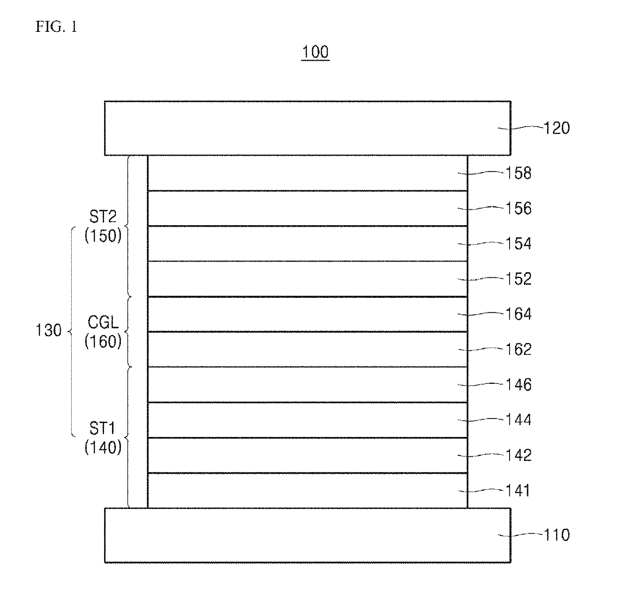
Fabrication of Tandem Organic Light Emitting Diode
[0206]In a vacuum chamber at a pressure of 5×10⁻⁸ to 7×10⁻⁸ torr, a tandem organic light emitting diode was fabricated by sequentially depositing the following layers on an indium-tin-oxide (ITO) substrate:
[0207]A hole injection layer (NPD-based host doped with 10 wt % of F4-TCNQ; 100 Å), a first hole transport layer (NPD-based compound; 1200 Å), a first light emitting material layer (blue light emitting material layer; anthracene-based host doped with 4 wt % of pyrene dopant; 200 Å), a first electron transport layer (1,3,5-tri[(3-pyridyl)-phen-3-yl]benzene (TmPyPB)-based compound; 100 Å), a first N-type charge generation layer (EN-m002 doped with 2 wt % of Li; 100 Å), a first P-type charge generation layer (NPD-based host doped with 10 wt % of F4-TCNQ; 200 Å), a second hole transport layer (NPD-based compound; 200 Å), a second light emitting material layer (yellow light emitting material layer; CBP-based host doped with Ir complex; ...
example 2
Fabrication of Tandem Organic Light Emitting Diode
[0209]A tandem organic light emitting diode was fabricated in the same manner as in Example 1 except that, as a host for the first and second N-type charge generation layers, EN-m005 prepared in Preparative Example 2 was used instead of EN-m002.
PUM
| Property | Measurement | Unit |
|---|---|---|
| thickness | aaaaa | aaaaa |
| thickness | aaaaa | aaaaa |
| thickness | aaaaa | aaaaa |
Abstract
Description
Claims
Application Information