Optical network communication system with optical line terminal transceiver and method of operation thereof

a technology of optical line terminal and optical network communication system, which is applied in the direction of multiplex communication, instruments, optical elements, etc., can solve the problems that the solution to these problems has long eluded those skilled in the ar

Active Publication Date: 2012-06-14
NEOPHOTONICS CORP
View PDF9 Cites 42 Cited by
  • Summary
  • Abstract
  • Description
  • Claims
  • Application Information

AI Technical Summary

Benefits of technology

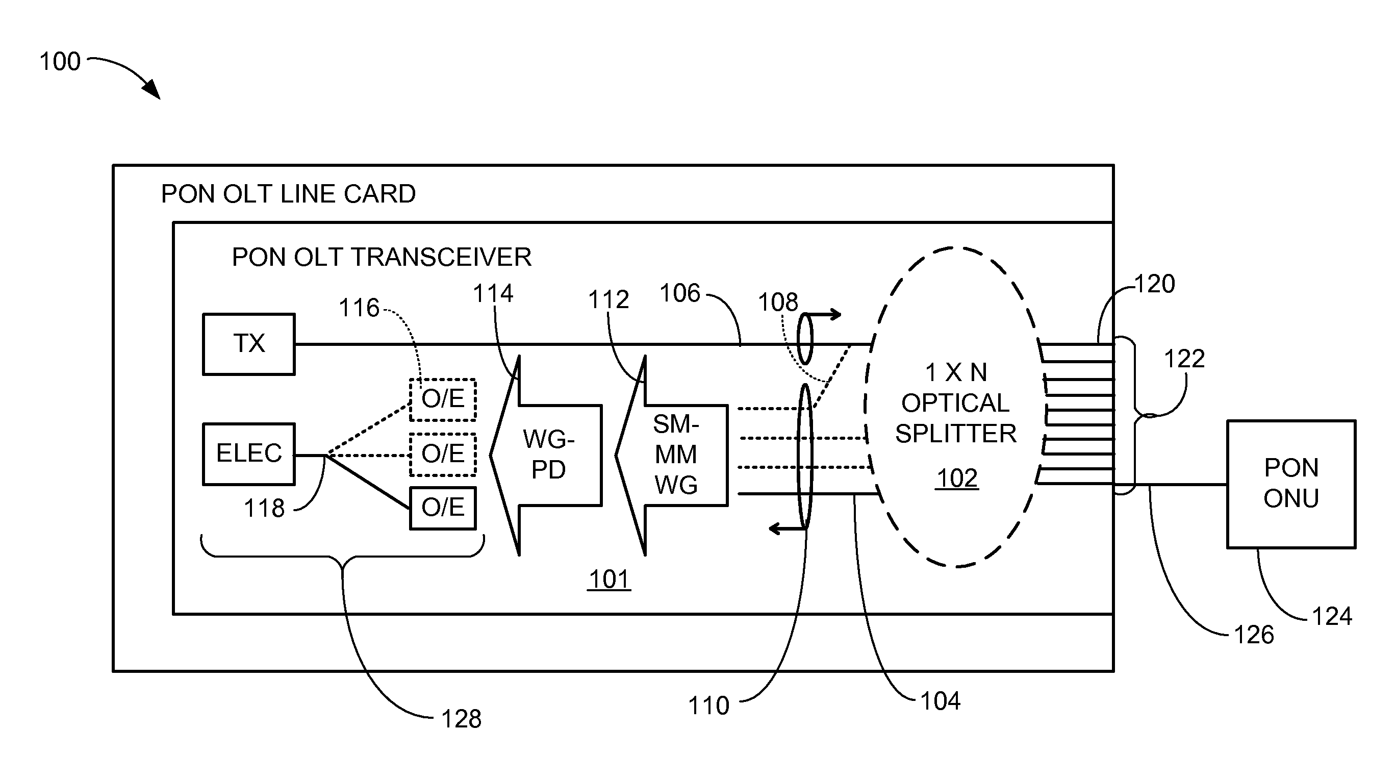
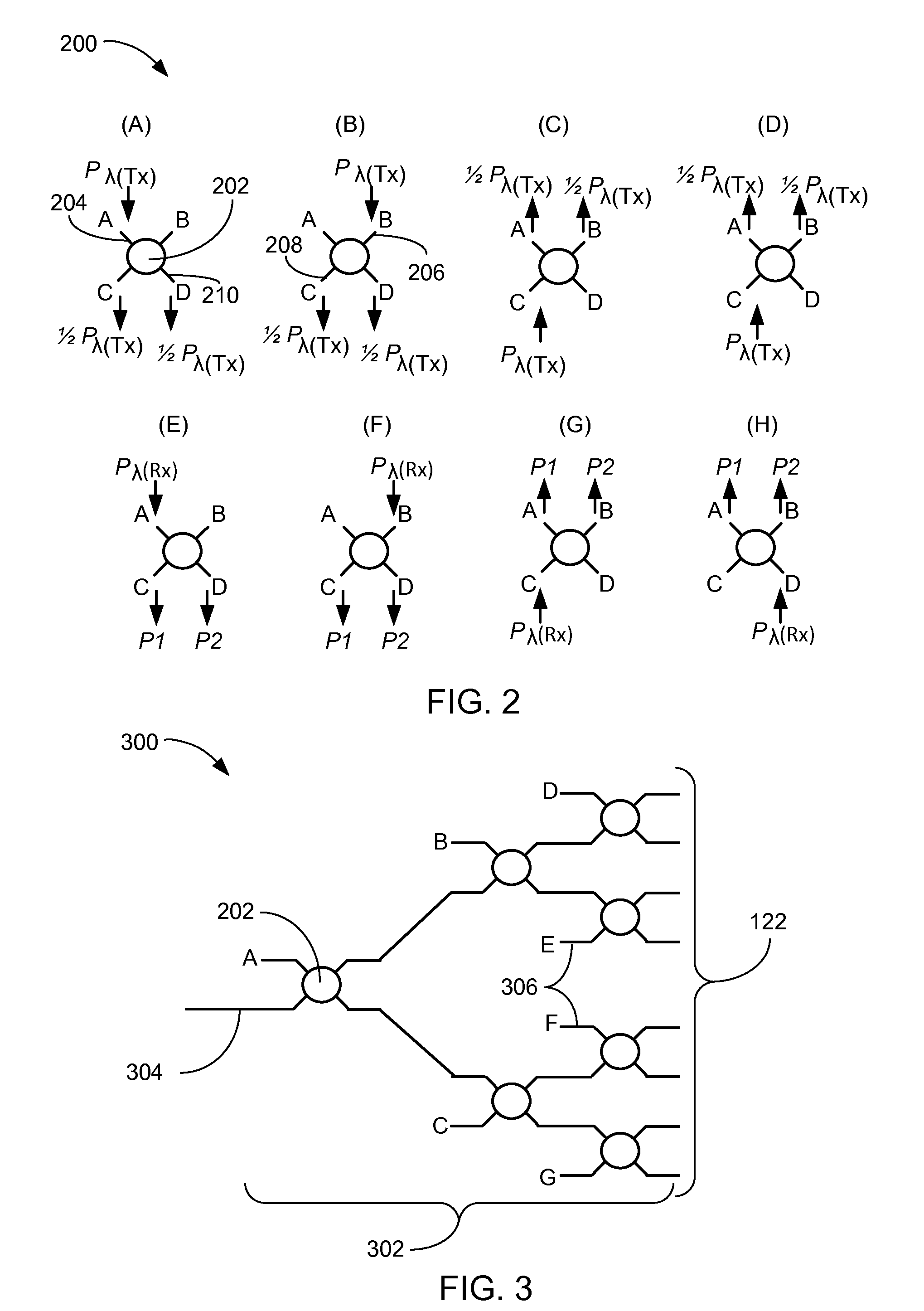
[0009]The present invention provides a method of operation of an optical network communication system including: providing a planar lightwave circuit including: connecting 2×2 single-mode optical couplers in an array for forming a 1×N single-mode optical splitter / combiner, and routing harvesting ports to a receiver for collecting harvested-light, from two or more of the harvesting ports, in the receiver wherein one of more of the harvesting ports is from the 2×2 single-mode optical couplers; transmitting to an optical network unit through the planar lightwave circuit at a first wavelength; and interpreting a response from the optical network unit at a second wavelength through the harvested-light.

Problems solved by technology

Solutions to these problems have been long sought but prior developments have not taught or suggested any solutions and, thus, solutions to these problems have long eluded those skilled in the art.

Method used


Image

  • Optical network communication system with optical line terminal transceiver and method of operation thereof
  • Optical network communication system with optical line terminal transceiver and method of operation thereof
  • Optical network communication system with optical line terminal transceiver and method of operation thereof

Examples


second embodiment

[0108]Referring now to FIG. 8, therein is shown is a functional block diagram of a passive optical network optical line terminal line card 800 utilizing an external version of the planar lightwave circuit 502 in the present invention. The functional block diagram of the passive optical network optical line terminal line card 800 depicts a small form-factor pluggable module 802 having the primary interface 604, such as a small form-factor pluggable industry standard interface for passive optical network support. The primary interface 604 has an industry accepted specification for mechanical and electrical tolerances.

[0109]A Passive Optical Network mechanical interface 804 can have the electrical interface 606. In the prior art structure of a pluggable optical module (not shown) that is substantially similar to the small form-factor pluggable module 802, only one of the ONU-facing optical ports 122 was provided. This prior art limitation causes additional hardware, space, and power to...

third embodiment

[0114]Referring now to FIG. 9, therein is shown a functional block diagram of a passive optical network optical line terminal line card 900 utilizing the external version of the planar lightwave circuit 502 in the present invention. The functional block diagram of the passive optical network optical line terminal line card 900 depicts the small form-factor pluggable module 902 having the primary interface 604, such as a small form-factor pluggable industry standard interface for passive optical network support. The primary interface 604 has an industry accepted specification for mechanical and electrical tolerances.

[0115]The Passive Optical Network mechanical interface 804 may have the electrical interface 606.

[0116]In the third embodiment of the present invention, the small form-factor pluggable module 902 may include the optical line terminal electrical circuit 610 that manages the transmission and receiving of the data between the small form-factor pluggable module 902 and the op...

fourth embodiment

[0119]Referring now to FIG. 10, therein is shown a functional block diagram of a passive optical network optical line terminal line card 1000 utilizing the planar lightwave circuit in the present invention. The functional block diagram of the passive optical network optical line terminal line card 1000 depicts the small form-factor pluggable module 608 having the primary interface 604, such as a small form-factor pluggable industry standard interface for passive optical network support. The primary interface 604 has an industry accepted specification for mechanical and electrical tolerances.

[0120]The small form-factor pluggable mechanical interface 602 may have the electrical interface 606. The electrical interface 606 is intended to allow replacement of the small form-factor pluggable module 608.

[0121]In a fourth embodiment of the present invention, the small form-factor pluggable module 608 may include the optical line terminal electrical circuit 610 that manages the transmission ...


PUM


Abstract

A method of operation of an optical network communication system including: providing a planar lightwave circuit including: connecting 2×2 single-mode optical couplers in an array for forming a 1×N single-mode optical splitter/combiner, and routing harvesting ports to an optical line terminal receiver for collecting harvested-light, from two or more of the harvesting ports, in the optical line terminal receiver wherein one of more of the harvesting ports is from the 2×2 single-mode optical couplers; transmitting to an optical network unit through the planar lightwave circuit at a first wavelength; and interpreting a response from the optical network unit at a second wavelength through the harvested-light.

Description

TECHNICAL FIELD[0001]The present invention relates generally to an optical network communication system, and more particularly to a system for providing a passive optical network.BACKGROUND ART[0002]An example of a point-to-multipoint optical network can be the passive optical network. Passive optical networks are defined in standards, by well known organizations, for general application. The network is terminated at a single point, typically located in a telecommunications provider central office (CO), in an optical line terminal (OLT) and at multiple subscriber points, typically at the subscriber's residence, by an optical network unit (ONU).[0003]The OLT and the ONUs have single fiber interfaces which transmit and receive optical signals at different wavelengths. The OLT transmits signals at a wavelength λdown and receives signals from the ONUs at a wavelength λup. The ONU transmits signals at a wavelength λup and receives signals from the OLT at a wavelength λdown. The downstrea...

Claims


Application Information

Patent Timeline
Patent Type & Authority Applications(United States)
IPC IPC(8): H04B10/20H04J14/02
CPCH04Q11/0067G02B6/125G02B6/28G02B6/2938G02B6/4246G02B6/4261G02B2006/1215G02B2006/12164H04B10/07H04B10/25H04J14/02G02B6/2808H04Q11/0005H04Q2011/0015
Inventor PIEHLER, DAVIDTICKNOR, ANTHONY J.
Owner NEOPHOTONICS CORP
Why Eureka
Try Eureka