Portable electronic device

a technology of electronic devices and lenses, applied in the field of display lenses, can solve the problems of poor dynamic response of display lenses

Inactive Publication Date: 2012-06-14
GOOGLE TECH HLDG LLC
View PDF3 Cites 85 Cited by
  • Summary
  • Abstract
  • Description
  • Claims
  • Application Information

AI Technical Summary

Problems solved by technology

More often than not it is because those skilled in the art have long recognized th

Method used


Image

  • Portable electronic device
  • Portable electronic device
  • Portable electronic device

Examples


Embodiment Construction

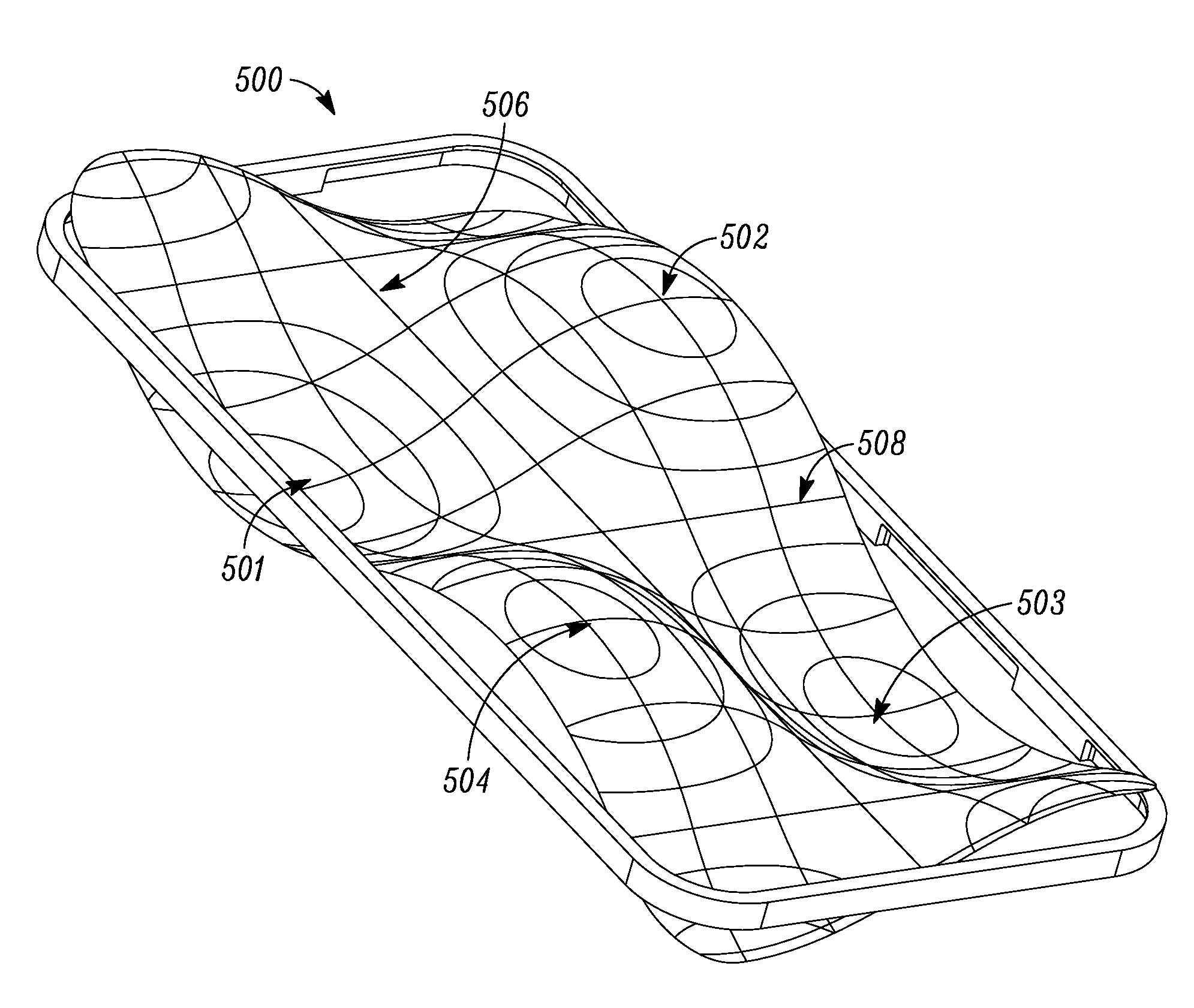
[0026]The portable electronic device described herein includes a free floating display lens that has a stiffener ring mounted on a peripheral region or edge of the free floating display lens to affect modal density and modal distribution of the free floating display lens. In addition, a piezoelectric supporting structure is attached to the stiffener ring. The piezoelectric supporting structure surrounds a display, and is electrically driven to produce an acoustic signal in one mode and a vibratory haptic signal in another mode.

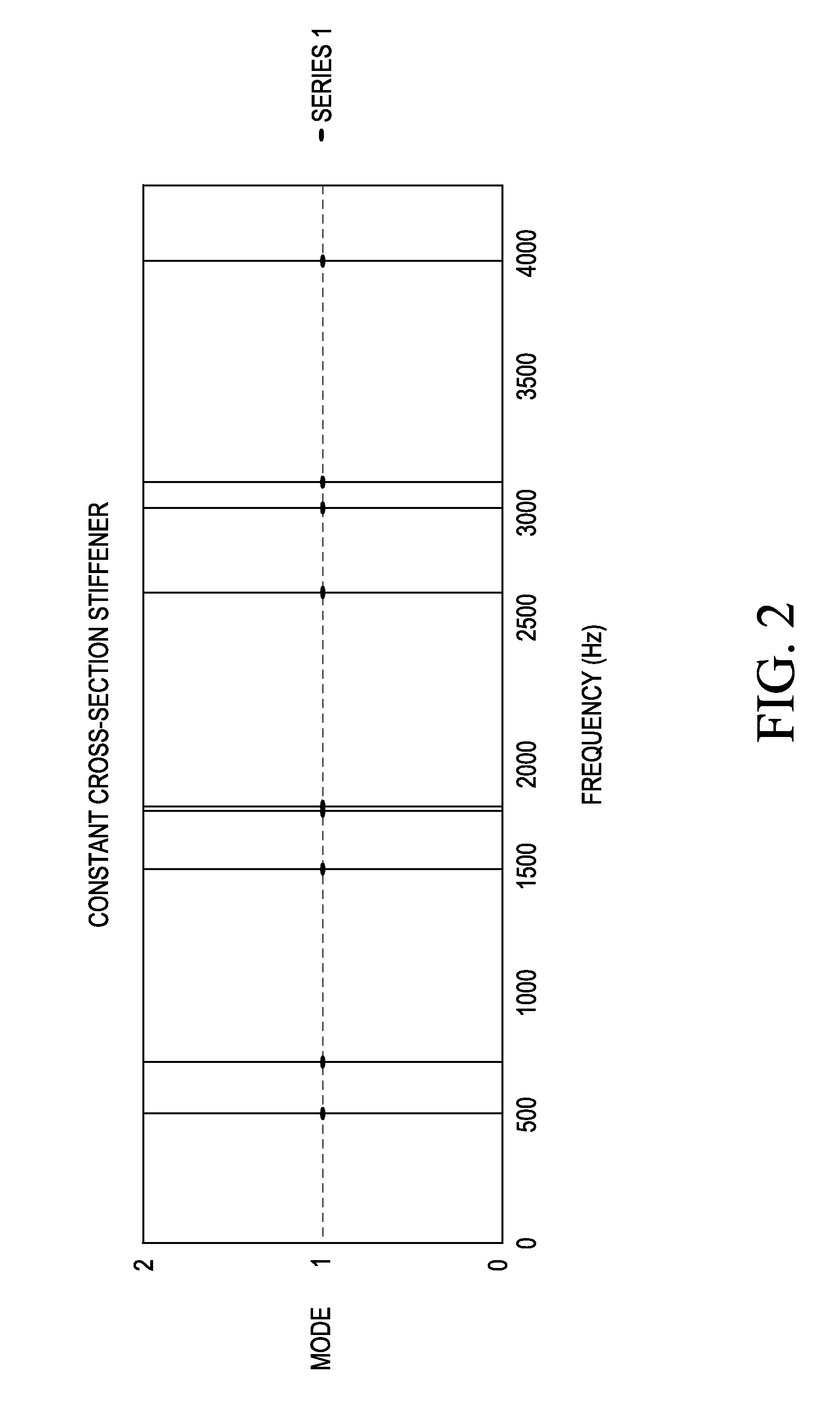
[0027]Referring to FIG. 2, modal density and modal distribution of a display lens were improved by adding a rigid or stiff ring around an outer edge of a display lens for a portable electronic device, for example, a mobile phone, a netbook computer, or a tablet portable computer. This rigid ring acts to stiffen the entire display lens, resulting in an upward shift of the display lens' modes, and will hereafter be referred to as a stiffener ring. The use of a s...


PUM


Abstract

A portable electronic device includes a free floating display lens having a stiffener ring mounted on a peripheral region or edge of the free floating display lens to affect modal density and modal distribution of the free floating display lens. Additionally, a piezoelectric supporting structure is attached to the stiffener ring, while surrounding a display, wherein the piezoelectric supporting structure is electrically driven to produce an acoustic signal in one mode and a vibratory haptic signal in another mode.

Description

FIELD OF THE INVENTION[0001]The present invention relates generally to using a display lens of a portable electronic device as an acoustic apparatus, while still allowing a large viewable area for a display. More specifically, the display lens is driven by an electrical signal to produce a substantial usable audio area particularly for private and speakerphone mode conversations. Additionally, the substantial usable audio area can also provide haptic feedback.BACKGROUND OF THE INVENTION[0002]Conventionally, the dimensions of a display lens for a portable electronic device, such as a mobile phone, are driven by the desired viewable display area and the industrial design of the phone. Therefore, the display lens is not often thought of as an acoustic apparatus or speaker. More often than not it is because those skilled in the art have long recognized that a display lens often has a poor dynamic response due to its physical dimensions.[0003]The configurations of conventional mobile pho...

Claims


Application Information

Patent Timeline
IPC IPC(8): H04B1/38
CPCH04M1/0266H04M1/185H04R2499/15H04R2499/11H04R7/18H04M1/03
Inventor ZUREK, ROBERT A.DAI, STEVE X.STEUER, PAUL R.
Owner GOOGLE TECH HLDG LLC
Why Eureka
Try Eureka