Engagement Control Assembly for a Bi-Directional Overrunning Clutch

a control assembly and clutch technology, applied in the field of clutches, can solve problems such as the dragging or advance of the rolling cag

Active Publication Date: 2012-06-21
HILLIARD
View PDF7 Cites 43 Cited by
  • Summary
  • Abstract
  • Description
  • Claims
  • Application Information

AI Technical Summary

Benefits of technology

[0020]The differential is preferably mounted to a vehicle that includes a primary drive axle and a secondary drive axle with two half shafts, each half shaft having one end engaged with a wheel and the opposite end engaged with the output hub. A control system is provided for activating the electromechanical device to engage the input shaft to the output hub.

Problems solved by technology

When the coil is energized, an electromagnetic field is produced which hinders the rotation of the armature plate, thus causing the roll cage to drag or advance into an appropriate position relative a clutch housing.

Method used


Image

  • Engagement Control Assembly for a Bi-Directional Overrunning Clutch
  • Engagement Control Assembly for a Bi-Directional Overrunning Clutch
  • Engagement Control Assembly for a Bi-Directional Overrunning Clutch

Examples


first embodiment

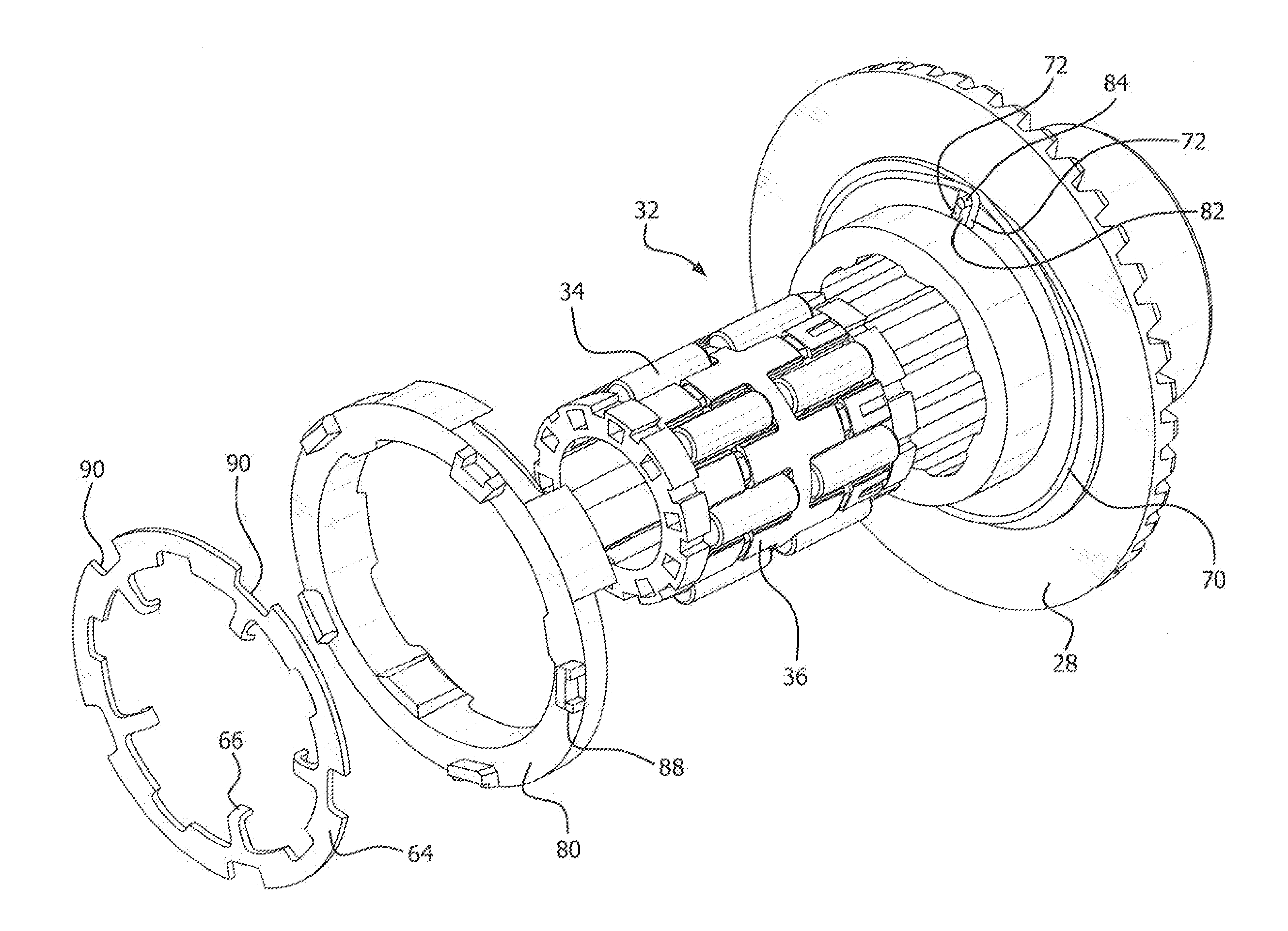
[0053]Referring to FIGS. 7-11B, another embodiment of the engagement control assembly 60′ is shown which addresses many of the limitations of the In this embodiment, instead of the torsion spring 70 being mounted within a groove in the clutch housing 28, it is position around an external surface of the clutch housing 28. More particularly, the assembly includes an adapter 80 which provides a connection between the torsion spring 70 and the roll cage 36. In this embodiment, the ends of the torsion spring overlap such that the arms 72 on the torsion spring 70 extend past one another defining a gap 82. The torsion spring is placed around a section of the clutch housing such that a pin 84 protruding outward from the clutch housing 28 is captured in the gap 82 with the arms on either side of the pin. See, FIG. 8.

[0054]The adapter or spring retainer 80 has an adapter pin 86 formed on the side of the adapter that faces the clutch housing. With the roll cage 36 positioned within the housin...

embodiment 60

[0057]The engagement control assembly 60′ shown in FIGS. 7-11B eliminates the above mentioned limitations of the embodiment 60. In this embodiment of the engagement control assembly 60′, the torsion spring 70 does not bias roll cage 36 off center. This allows the roll cage 36 to remain centered during engagement and disengagement of bidirectional overrunning clutch 20. Each roll 34 engages or disengages their respective inner cam surface 30 simultaneously providing a more efficient operation. Outer lugs 88 on adapter 80 have a dual function. First they transmit torque from armature plate notches 90 into the lugs 88, which in turn transmit the torque to the torsion spring 70 through pin 86. Second, the adapter 80 centers the armature plate 64 by aligning lugs 88 into armature plate notches 90. The adapter lugs 88 pilot into the engagement control assembly 60. This provides the bidirectional overrunning clutch 20 with consistent torque transfer.

[0058]The adapter 80 also includes inner...


PUM


Abstract

A bi-directional overrunning clutch differential for controlling torque transmission between a pinion input shaft and at least one output hub. The clutch having a clutch housing and the roll cage mounted within the housing. An engagement control assembly is provided for controlling the relative position of the roll cage with respect to a cam surface on the clutch housing. The engagement control assembly includes an electronically controlled actuation device, such as a coil or solenoid, which when activated causes the roll cage to rotate into a second position relative to the clutch housing to engage the rolls with the cam surface and an outer surface of the hub. A spring is engaged with the clutch housing and has an end engaged with the roll cage for biasing the roll cage into a neutral position when the roll cage is in its second position.

Description

FIELD OF THE INVENTION[0001]The present invention is directed to clutches and, more particularly, an engagement control assembly for a bi-directional overrunning clutch for controlling engagement and disengagement of the clutch.BACKGROUND OF THE INVENTION[0002]In recent years bi-directional overrunning clutches have been incorporated into various drive systems to replace conventional differentials. Conventional differentials include: open, limited slip, locking and center differentials. U.S. Pat. No. RE38,012, commonly owned by the assignee of the present invention, describes a bi-directional overrunning clutch for controlling torque transmission between a secondary drive shaft and secondary driven shafts. This transmission system is beneficial in four wheel drive vehicles where it is desirable to be able to engage and disengage the secondary driven shafts in different driving environments. The system described in U.S. Pat. No. RE38,012 includes an innovative system to advance and / o...

Claims


Application Information

Patent Timeline
Patent Type & Authority Applications(United States)
IPC IPC(8): F16D27/02F16D41/064
CPCF16D27/10Y10T74/19005F16D41/088
Inventor BREWER, J. BRENDANHEALTH, KELLY P.PALMER, JAMES E.KNICKERBOCKER, HOWARD J.HASSON, JR., JOHN MICHAEL
Owner HILLIARD
Why Eureka
Try Eureka