Power transmission

a transmission and power technology, applied in mechanical actuated clutches, gearing, hoisting equipments, etc., can solve the problems of waste of energy of the driving engine of the vehicle, and achieve the effects of reducing or eliminating likelih, torque limiter, and more stable movement of the plunger

a transmission and power technology, applied in mechanical actuated clutches, gearing, hoisting equipments, etc., can solve the problems of waste of energy of the driving engine of the vehicle, and achieve the effects of reducing or eliminating likelih, torque limiter, and more stable movement of the plunger

US7153228B2Inactive Publication Date: 2006-12-26SANDEN CORP

Image

  • Power transmission
  • Power transmission
  • Power transmission

Examples


Embodiment Construction

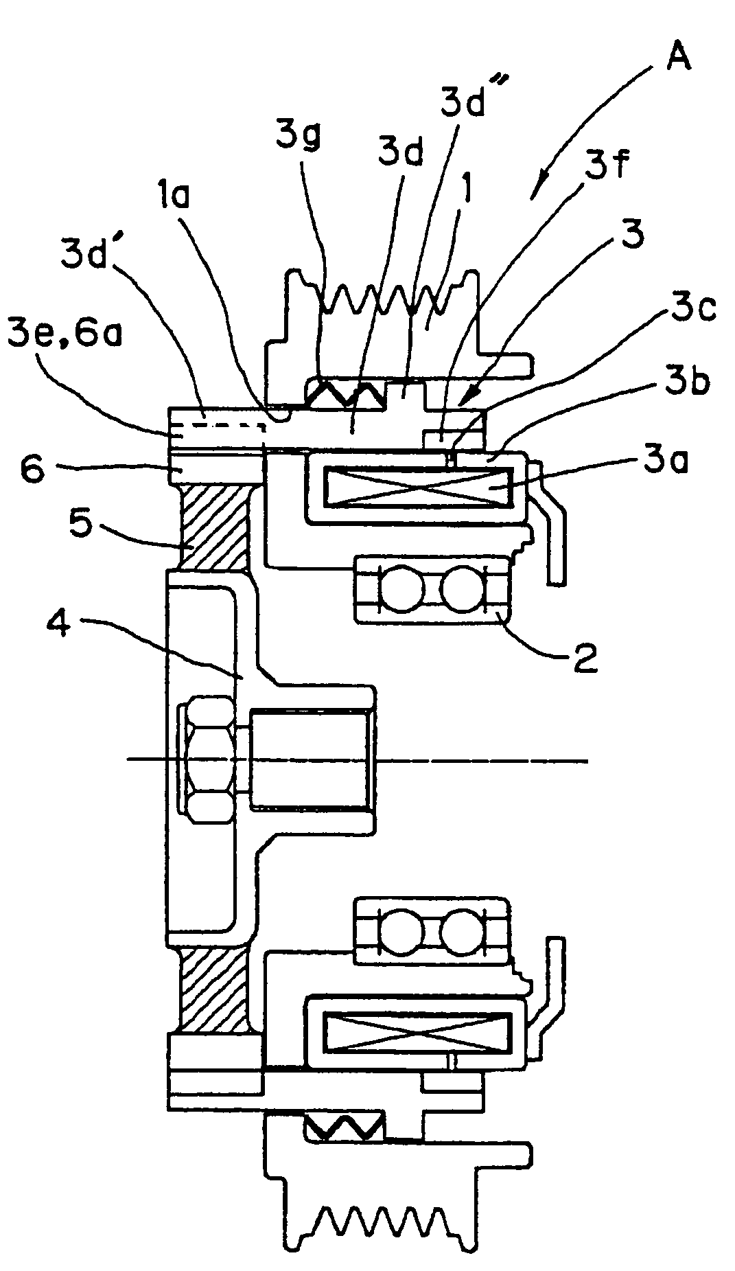
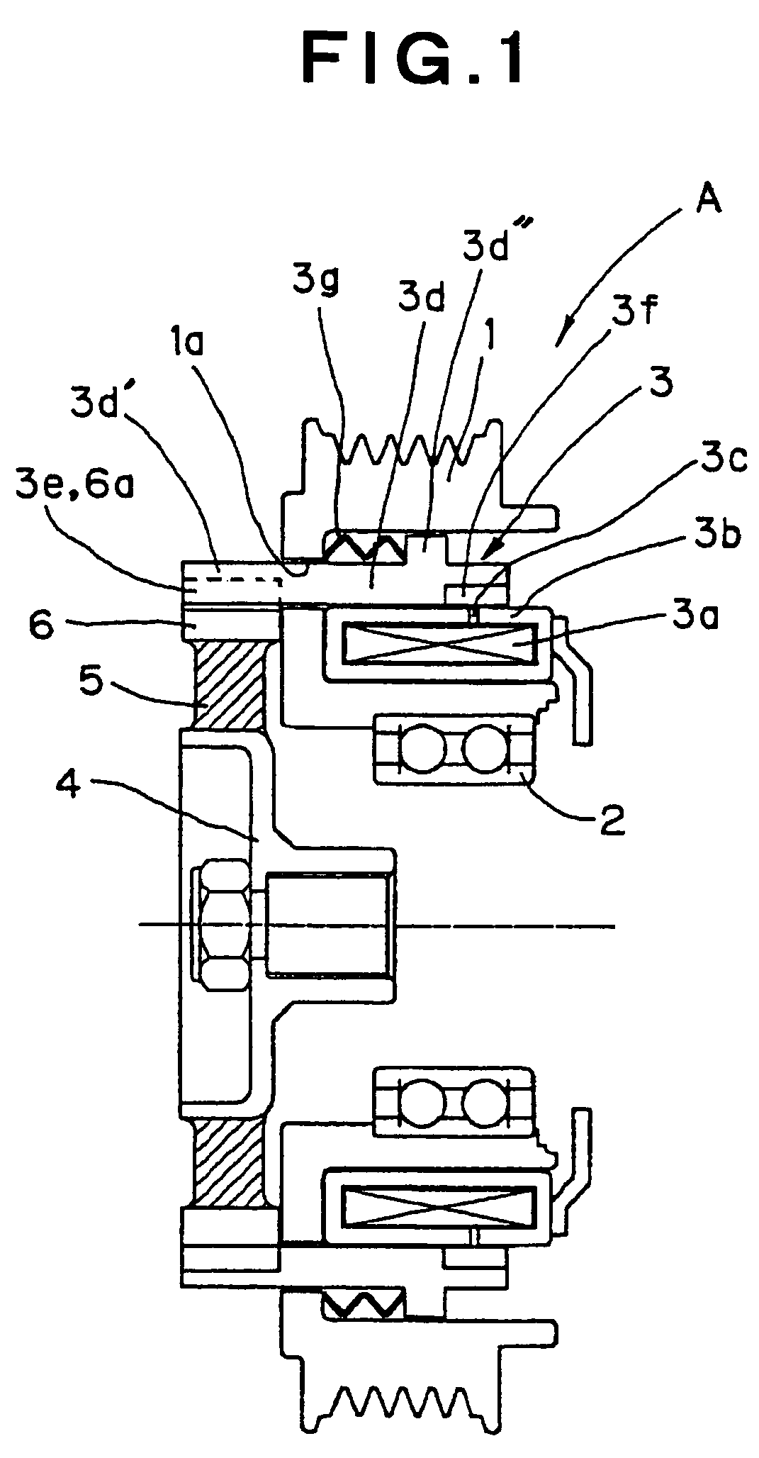
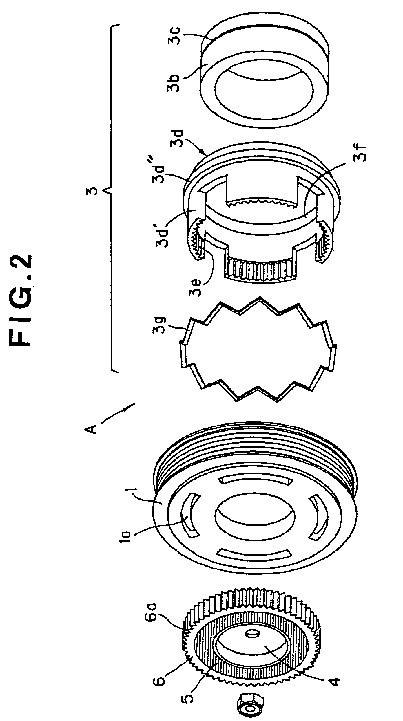
[0019]FIGS. 1 and 2 depict a power transmission according to an embodiment of the present invention applied to an external signal controlled-type compressor used in an air conditioning system for vehicles. As depicted in FIGS. 1 and 2, a power transmission A comprises an annular pulley 1 as a first rotating member, e.g., an annular pulley 1, which a U-shaped cross section. Pulley 1 may be connected to an engine (not shown) of a vehicle, and the engine may be used as an external drive source via a belt, band, cable, chain, or the like (not shown). Pulley 1 may be supported by a casing (not shown) of an external signal control-type compressor via a bearing 2.

[0020]An electromagnetic solenoid 3 may be provided within pulley 1. Electromagnetic solenoid 3 may have a coil 3a and an annular yoke 3b having a rectangular, hollow, cross-section which contains the coil 3a. Yoke 3b may be fixed to the casing of the external signal controlled-type compressor. A slit 3c may be formed in the outer...


PUM


Abstract

A power transmission includes a first rotating member driven by an external drive source, an electromagnetic solenoid provided to the first rotating member, a second rotating member fixed to a main shaft of a rotary apparatus, and an mechanism for engaging and disengaging a plunger of the electromagnetic solenoid from the second rotating member. When the rotary apparatus is not used, the energy of the external drive source may be prevented from being wasted by interrupting the torque transmission from the first rotating member to the second rotating member by the operation of the mechanism for engaging and disengaging.

Description

BACKGROUND OF THE INVENTION[0001]1. Field of the Invention[0002]The present invention relates to a power transmission, and more particularly, to a power transmission suitable for a drive mechanism of a compressor used in an air conditioning system for vehicles.[0003]2. Description of Related Art[0004]In a known external signal controlled-type compressor used in an air conditioning system for vehicles such as the compressor shown in Japanese Patent Application No. JP-A-6-34684, the compressor's displacement is controlled by an external signal, and the compressor is connected directly to and driven by an engine. In the known external signal controlled-type compressor, when the air conditioning system is not in operation, the engine drive the compressor at a minimum displacement. Nevertheless, because the compressor is in operation and the engine drives a rotating member of the compressor when the a / c system is not in operation, the energy of the driving engine of the vehicle is wasted...

Claims


Application Information

Patent Timeline
26 Dec 2006
Publication
US7153228B2
IPC
F16H63/00; F16H55/36; B62M9/00; F16D27/118
CPC
F16D27/118; F16H2055/366
Inventors
FUJIU, HIDEAKI; GONDA, HIDEYUKI