Circuit breaker

a circuit breaker and circuit technology, applied in the field of circuit breakers, can solve problems such as the limitation of the adjustment of bimetal, and achieve the effects of reducing material cost, reducing component structure changes, and increasing thermal conductivity of the entire stud

Inactive Publication Date: 2012-06-21
FUJI ELECTRIC FA COMPONENTS & SYST CO LTD
View PDF6 Cites 10 Cited by
  • Summary
  • Abstract
  • Description
  • Claims
  • Application Information

AI Technical Summary

Benefits of technology

[0018]As can be seen from the above description, according to the invention, for example, when the material forming the stud is changed, the dimensions of the base portion inserted into the stud insertion hole which is provided in the case are not changed, and the cross-sectional area of only a portion (protruding portion) of the base portion which is not inserted into the stud insertion hole increases, thereby ensuring thermal conduction. Therefore, it is not necessary to change the dimensions of the stud insertion hole formed in the case. As a result, it is possible to provide a circuit breaker capable of minimizing a change in the structure of a component even when the material (thermal conductivity...

Problems solved by technology

However, there is a limitatio...

Method used


Image

  • Circuit breaker
  • Circuit breaker
  • Circuit breaker

Examples


first embodiment

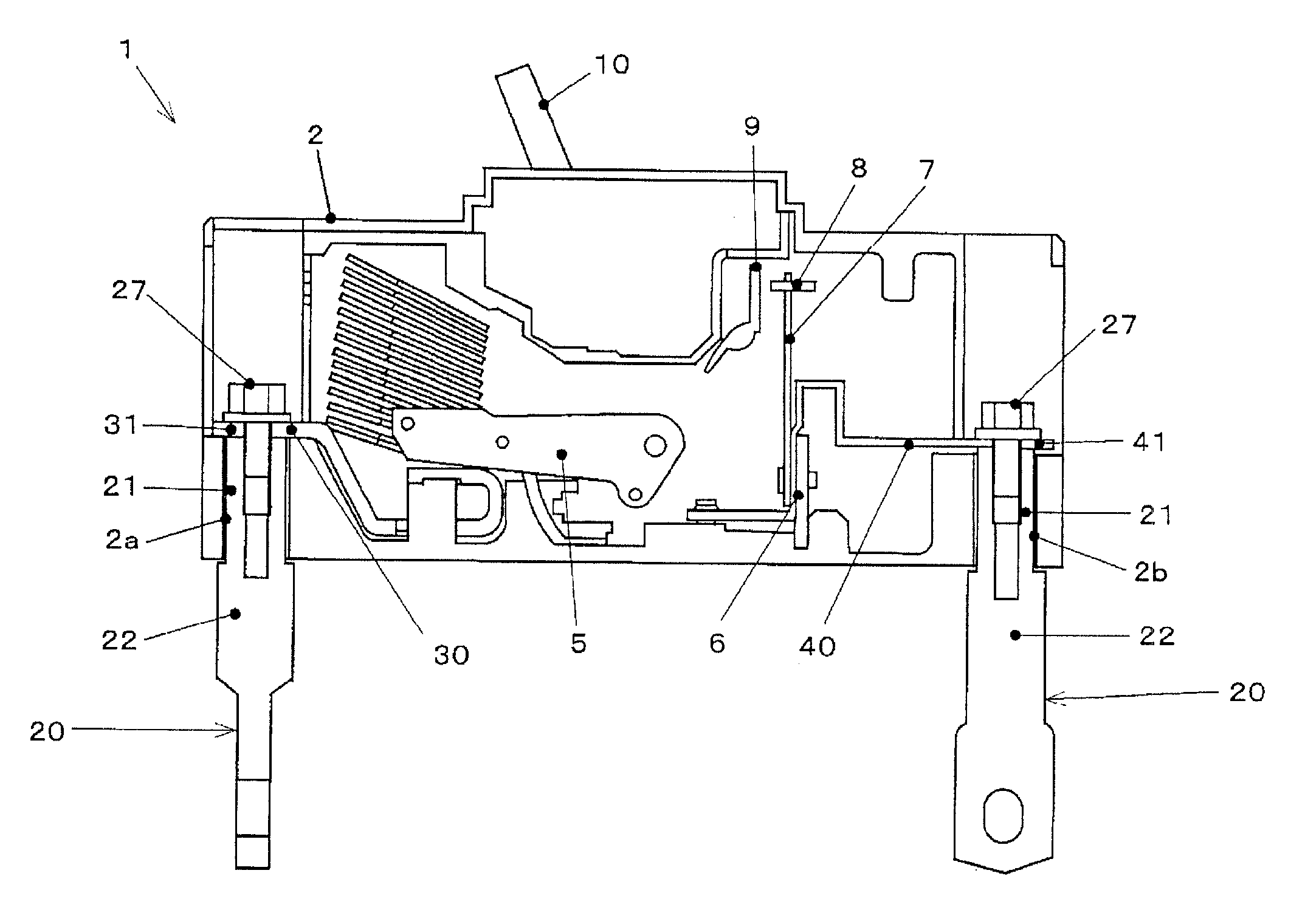
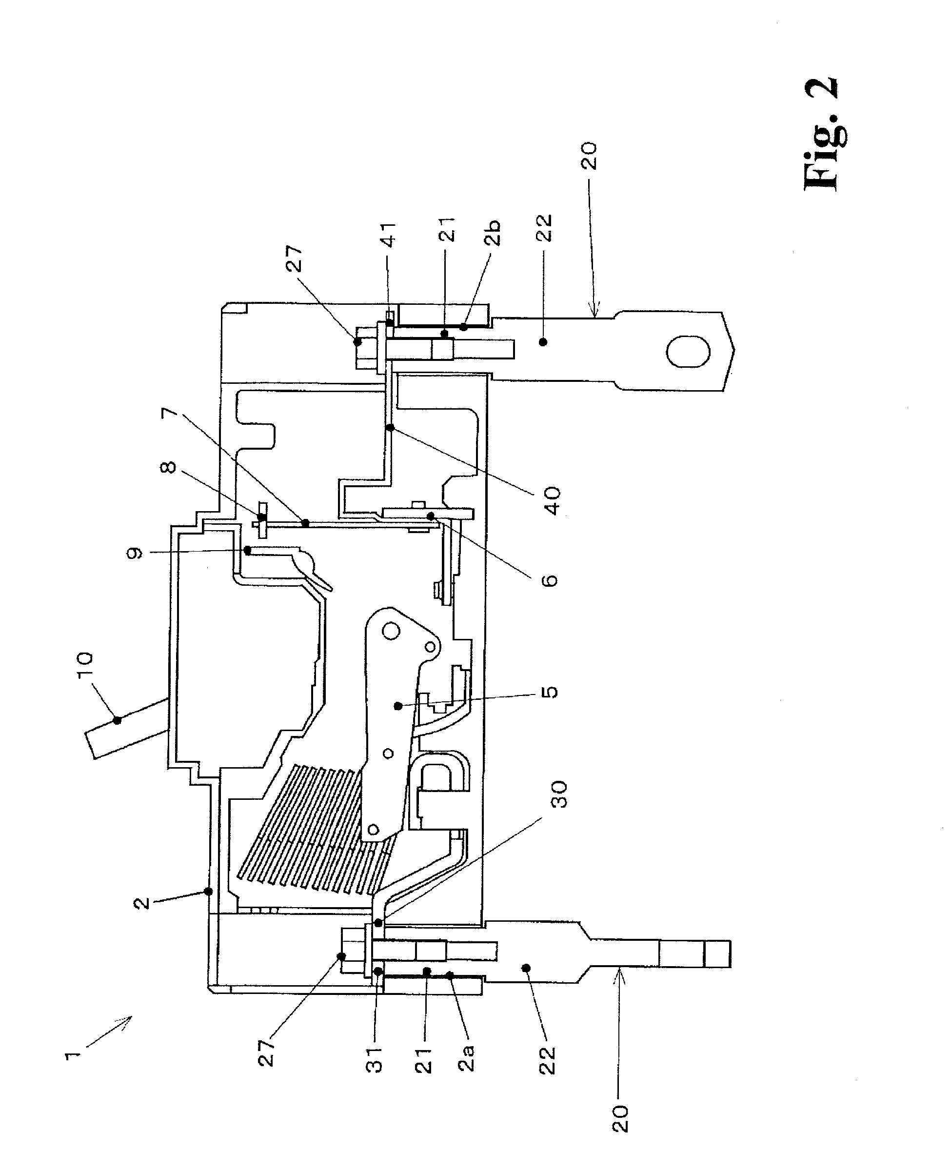
[0027]As shown in FIG. 2 or FIG. 3, a circuit breaker 1 includes a case 2 with a rectangular parallelepiped shape. For example, a breaking mechanism portion that breaks a circuit when a current with a predetermined value or more flows, and terminals 30 and 40 connected to the power supply side or the load side of the breaking mechanism portion are provided in the case 2. The breaking mechanism portion includes, for example, a movable contact 5, a heater 6, and a bimetal 7. When a voltage is applied, a current sequentially flows through the power-supply-side terminal 30, the movable contact 5, a connection conductor (not shown), the heater 6, and the load-side terminal 40 having one end connected to the heater 6. Studs 20 are attached to the power-supply-side terminal 30 and the load-side terminal 40, which will be described in detail below.

[0028]The case 2 is made of a synthetic resin with a good insulating property. A handle 10 for manual operation is provided on a front surface 2d...

second embodiment

[0040]Next, a circuit breaker according to a second embodiment of the invention will be described with reference to FIG. 4.

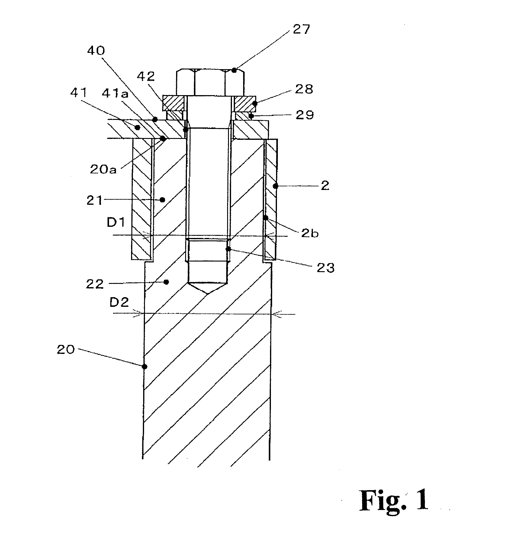
[0041]A stud 20A of the circuit breaker according to this embodiment includes a base portion 21 that is inserted into an insertion hole 2b of a case 2 and a protruding portion 22 protruding from the case 2. The diameter of the protruding portion 22 is more than that of the base portion 21. The stud 20A is formed by bonding two members, that is, a first member 50 that includes the base portion 21 and a part of the protruding portion 22 close to the base portion 21 and a second member 60 that includes the other part of the protruding portion 22. A screw hole 51 is provided in the end surface of the first member 50 so as to extend on the axis. The first member 50 is made of a material (for example, copper) with a high thermal conductivity and the second member 60 is made of a material (for example, aluminum) with a low thermal conductivity. The first member 50 and ...

third embodiment

[0045]Next, a circuit breaker according to a third embodiment of the invention will be described with reference to FIG. 5.

[0046]A stud 20B of the circuit breaker according to this embodiment includes a base portion 21 inserted into an insertion hole 2b of a case 2 and a protruding portion 22 protruding from the case 2. The diameter of the protruding portion 22 is more than that of the base portion 21. Similarly to the stud 20A according to the second embodiment, the stud 20B includes a first member 50 that includes the base portion 21 and a part of the protruding portion 22 close to the base portion 21 and a second member 60 that includes the other part of the protruding portion 22. In this embodiment, the stud 20B is formed by fastening and fixing two members 50 and 60. The first member 50 is made of a material (for example, copper) with a high thermal conductivity, and a through hole (clearance hole) 51 into which a screw 27 is inserted is formed on the axis in the first member 50...


PUM


Abstract

Provided is a circuit breaker capable of minimizing a change in the structure of, for example, a case even when a material (thermal conductivity) forming a stud is changed.
A stud (20) includes a base portion (21) that is provided in a case (2) and a protruding portion (22) that protrudes from the case (2). The cross-sectional area of the protruding portion (22) is more than that of the base portion (21). When the cross-sectional area of the protruding portion (22) is more than that of the base portion (21) in the stud (20), the thermal conductivity of the protruding portion (22) increases and it is possible to increase the thermal conductivity from the protruding portion (22) to an external conductor connected to the stud. In addition, since the surface area of the protruding portion (22) increases, the amount of heat dissipated from the protruding portion (22) increases. In this case, since the dimensions of the base portion (21) inserted into a stud insertion hole (2b) of the case (2) do not vary, it is not necessary to change the dimensions of the insertion hole (2b) of the case (2). Therefore, it is possible to minimize a change in the structure of a component even when the material forming the stud is changed.

Description

TECHNICAL FIELD[0001]The present invention relates to a circuit breaker, such as a molded circuit breaker or an earth leakage breaker. In particular, the present invention relates to an improved circuit breaker capable of minimizing a change in the structure of, for example, a case even when a material forming a stud is changed.BACKGROUND ART[0002]A circuit breaker breaks a circuit and prevents the damage of an electric wire or an apparatus when a current with a predetermined value or more flows due to, for example, an overload or a short circuit. The circuit breaker includes a breaking mechanism portion that breaks a circuit with a bimetal when a current with a predetermined value or more flows and a terminal connected to the power supply side or the load side of the breaking mechanism portion. The breaking mechanism portion and the terminal are provided in the case. A stud connected to a power-supply-side line and a stud connected to a load-side line contact and are fixed to a pow...

Claims


Application Information

Patent Timeline
IPC IPC(8): H01H9/02
CPCH01H9/52H01H71/16H01H73/20H01H71/08H01H73/02
Inventor NAKANO, MASAAKITOYAMA, KENTAROOSAWA, MAKOTO
Owner FUJI ELECTRIC FA COMPONENTS & SYST CO LTD
Why Eureka
Try Eureka