USB port detecting circuit

a technology of usb port and detection circuit, which is applied in the direction of pulse manipulation, pulse technique, instruments, etc., can solve the problem that the method is unable to detect whether the voltage of a usb port is within a certain, standard rang

Inactive Publication Date: 2012-06-21
HONG FU JIN PRECISION IND (SHENZHEN) CO LTD +1
View PDF18 Cites 13 Cited by
  • Summary
  • Abstract
  • Description
  • Claims
  • Application Information

AI Technical Summary

Problems solved by technology

However, this method requires plugging and unplugging the devices to or from the USB ports separately and frequently, which is labor

Method used


Image

  • USB port detecting circuit
  • USB port detecting circuit
  • USB port detecting circuit

Examples


Embodiment Construction

[0010]The disclosure is illustrated by way of example and not by way of limitation. In the accompanying drawings, like references indicate similar elements. It should be noted that references to “an” or “one” embodiment in this disclosure are not necessarily to the same embodiment, and such references mean at least one.

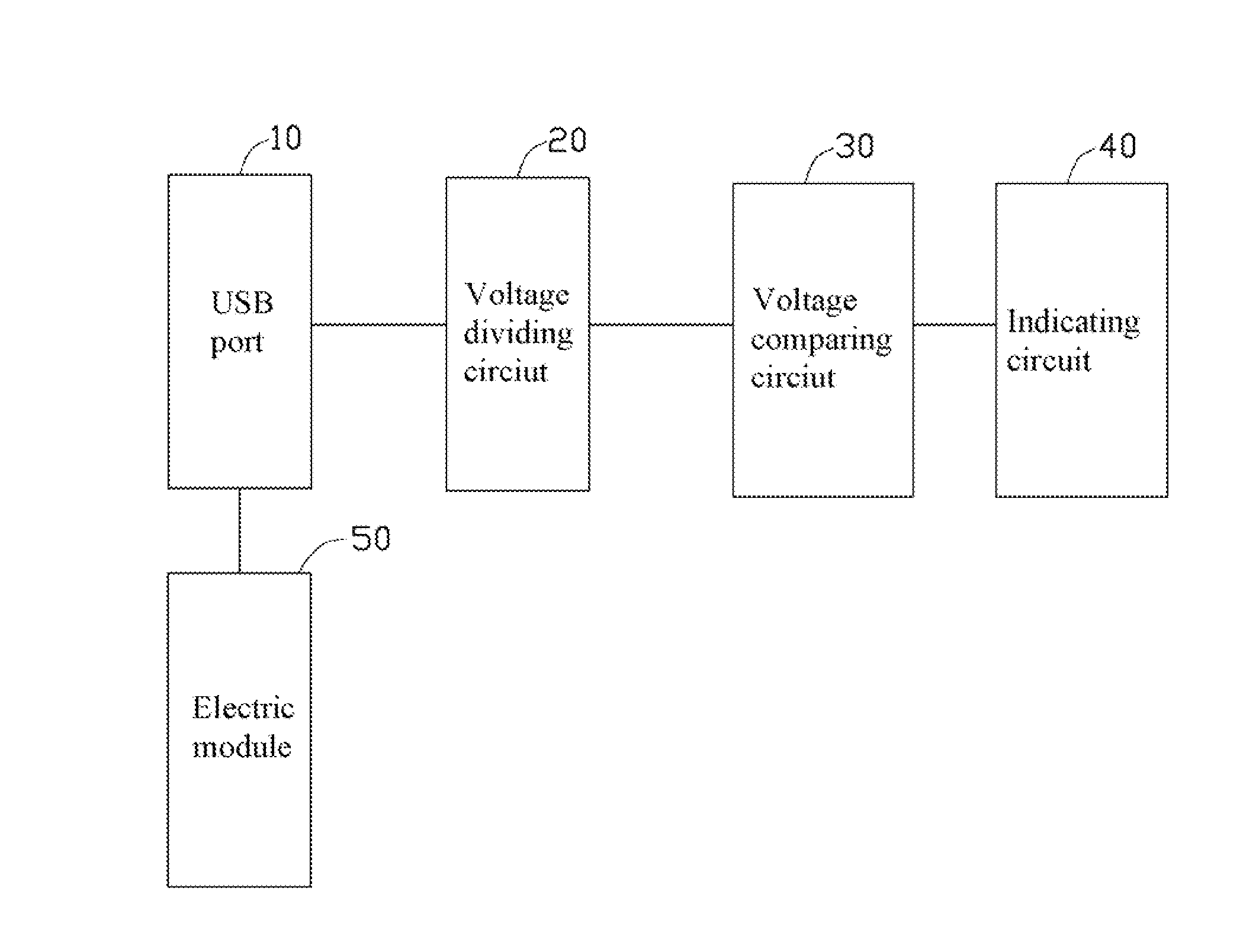
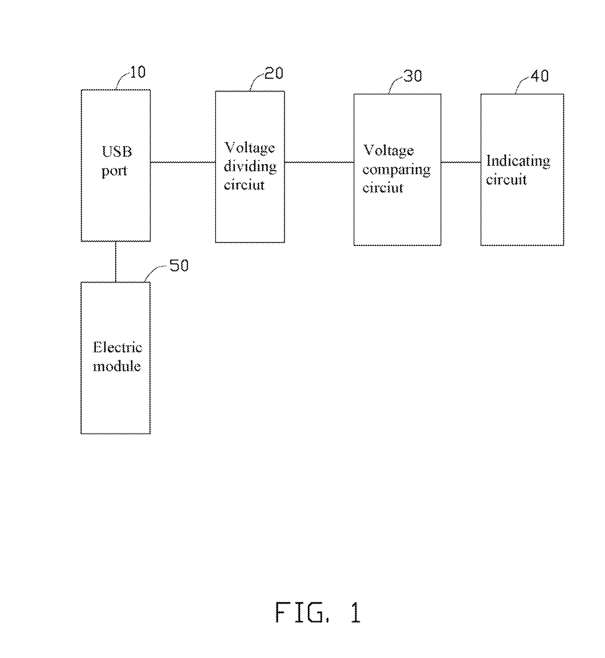
[0011]Referring to FIG. 1, an embodiment of a USB port detecting circuit is configured to test whether the voltage output of a USB port 10 of an electronic device (such as a computer) is within a standard range (e.g., 4.75V-5.25V). The USB port detecting circuit includes a voltage dividing circuit 20 connected to the USB port 10, a voltage comparing circuit 30 connected to the voltage dividing circuit 20, an indicating circuit 40 connected to the voltage comparing circuit 30, and an electric load 50 connected to the USB port 10.

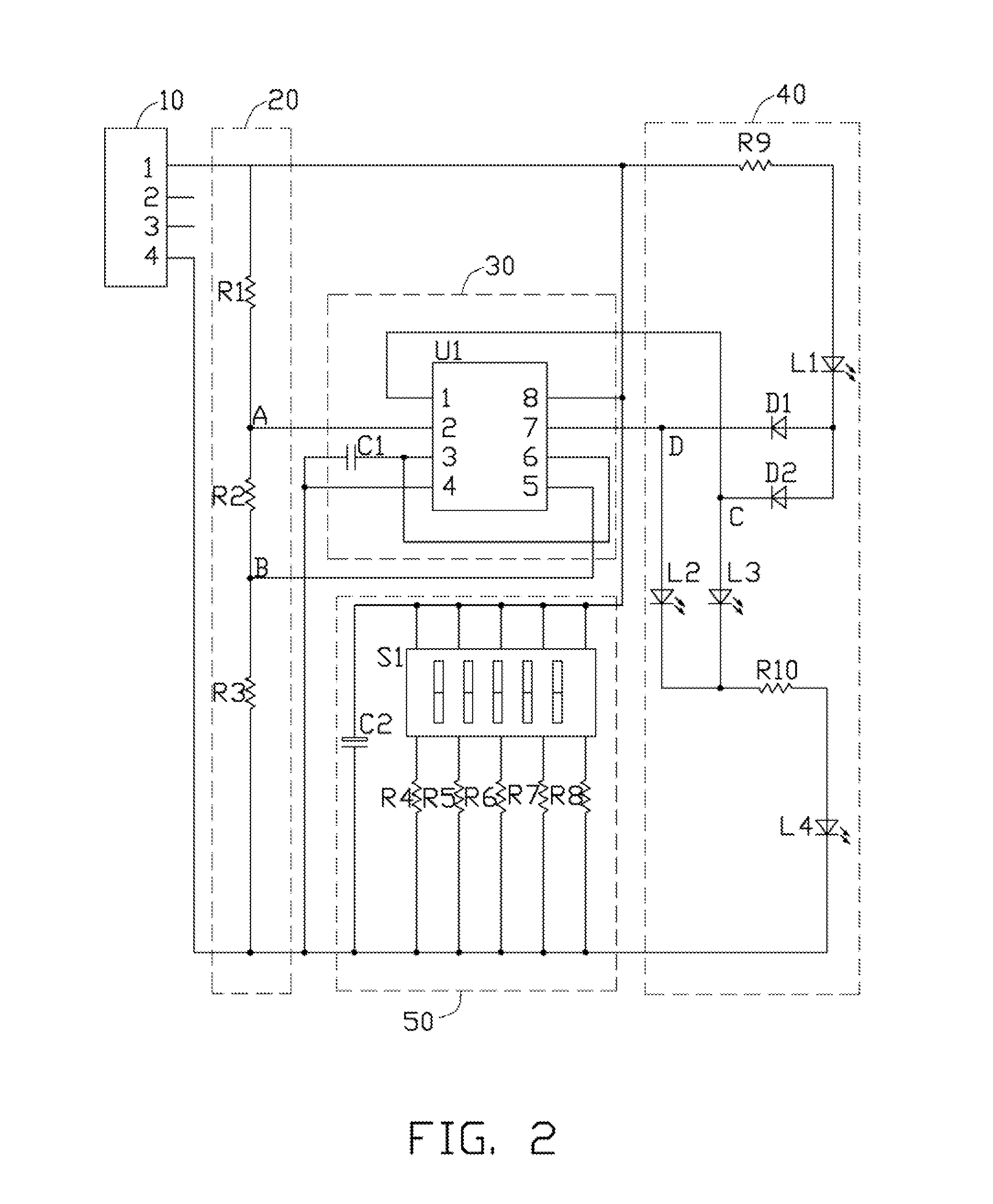
[0012]Referring to FIG. 2, the voltage dividing circuit 20 includes a first resistor R1, a second resistor R2, and a third resistor R3 which a...


PUM


Abstract

A Universal Series Bus USB port detection and testing circuit, configured to detect the voltage output of a USB port of an electronic device, includes a voltage comparing circuit and an indicating circuit. The indicating circuit is connected to an output terminal of the voltage comparing circuit. The voltage comparing circuit compares the voltage output from the USB port against a reference voltage and output a signal whereby the indicating circuit indicates whether the voltage is within, or above, or below, the standard range.

Description

BACKGROUND[0001]1. Technical Field[0002]The present disclosure relates to a Universal Series Bus (USB) port detecting circuit, and more particularly to a USB port detecting circuit capable of detecting whether the voltage of a USB port is within a standard range.[0003]2. Description of Related Art[0004]Today, USB technology is broadly applied in series communication solutions. Before selling or using electronic devices having USB ports, the USB ports need to be tested. A conventional method for testing the USB ports is to use some conventional USB devices such as mice, keyboards, hard disk drives, etc., to directly connect with the USB ports, and so judge whether the USB ports are functioning properly or not. However, this method requires plugging and unplugging the devices to or from the USB ports separately and frequently, which is laborious. Furthermore, the conventional method is unable to detect whether the voltage of a USB port is within a certain, standard range.[0005]Therefo...

Claims


Application Information

Patent Timeline
IPC IPC(8): H03K5/22
CPCG01R19/165G06F1/28G06F1/266
Inventor XIE, LING-YUXIE, XING-PING
Owner HONG FU JIN PRECISION IND (SHENZHEN) CO LTD
Why Eureka
Try Eureka