Multi-phase switching regulator

a voltage regulator and multi-phase technology, applied in the direction of power conversion systems, dc-dc conversion, instruments, etc., can solve the problems of sluggish and imprecise control of output voltage, unfavorable ic design, and processing delays

Inactive Publication Date: 2008-01-01
ANALOG DEVICES INC
View PDF11 Cites 174 Cited by
  • Summary
  • Abstract
  • Description
  • Claims
  • Application Information

AI Technical Summary

Benefits of technology

[0010]A multi-phase switching voltage regulator is presented which overcomes the problems noted above, enabling precise multiple-loop control which is particularly well suited to AVP power supplies.

Problems solved by technology

However, implementing any of the regulators cited above as a multi-phase regulator requires summing and / or sampling data in the controller IC, which can introduce unwanted complexity and processing delays into the IC design.
Another switching regulator issue concerns maintaining the output voltage within specified limits in response to load transients.
However, this approach can result in sluggish and imprecise control on the output voltage for dynamic changes in the load.

Method used


Image

  • Multi-phase switching regulator
  • Multi-phase switching regulator
  • Multi-phase switching regulator

Examples


Embodiment Construction

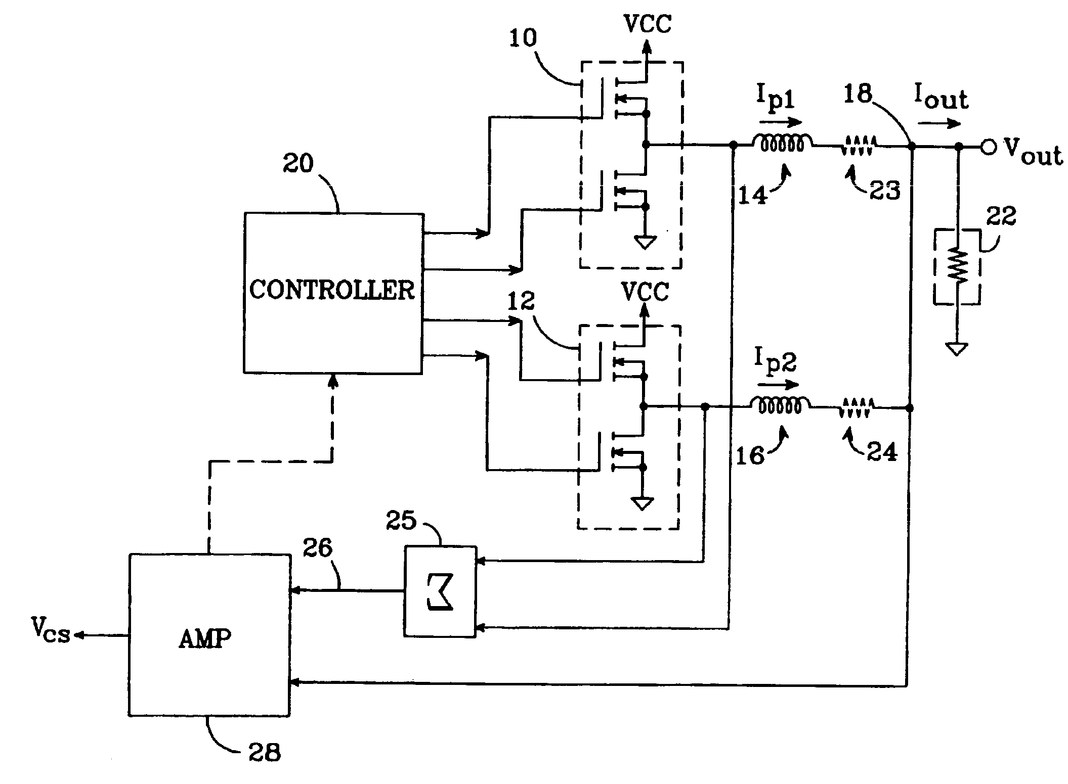
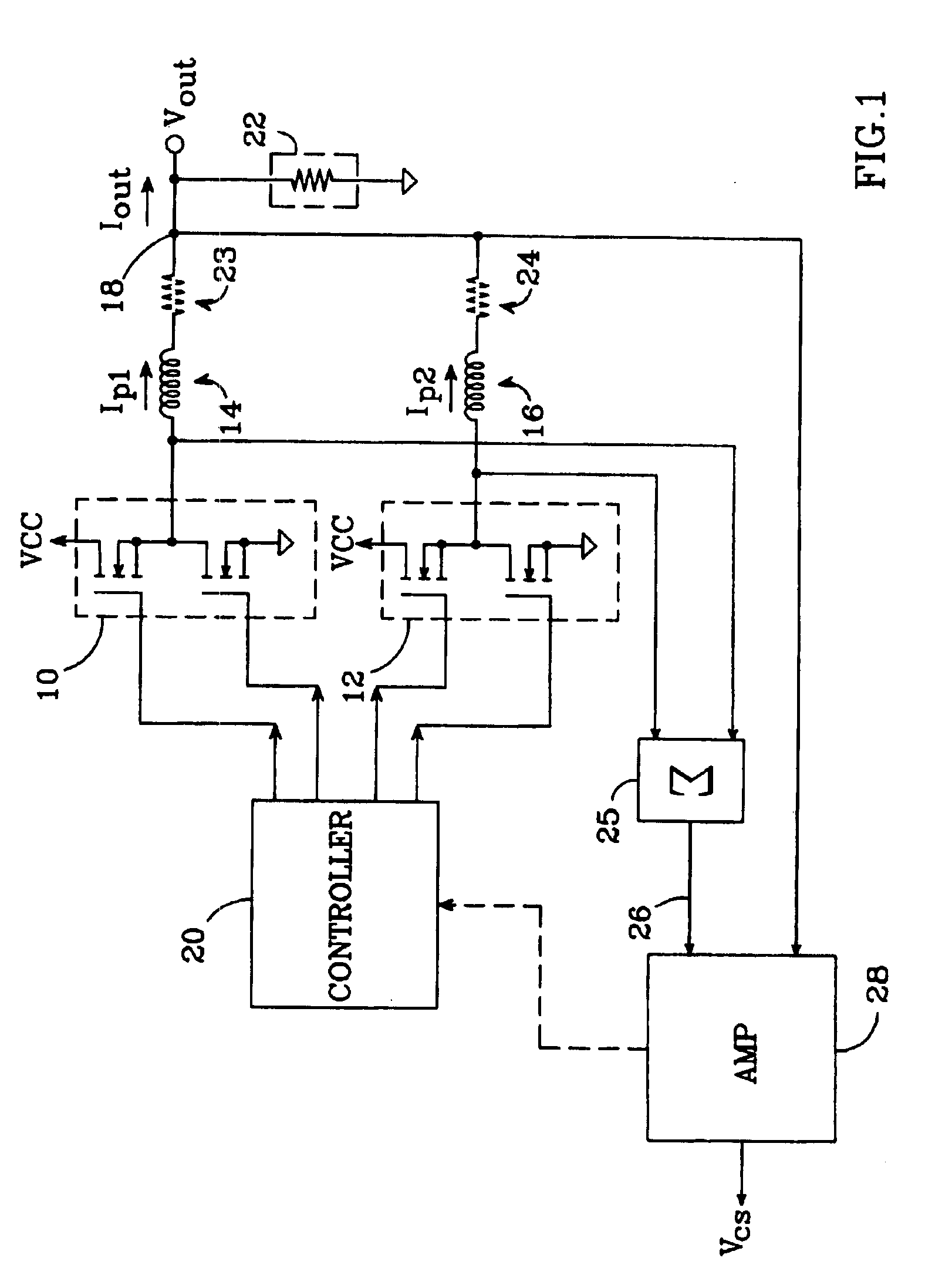
[0021]A schematic / block diagram illustrating the principles of a total current circuit for a multi-phase switching regulator in accordance with the present invention is shown in FIG. 1. The number of phases is identified herein as “N”; e.g., for the exemplary regulator shown in FIG. 1, N=2. For each phase, the regulator includes a switching element (10,12) made up of one or more switching transistors, with each switching element connected to the “switch node” side of a respective output inductor (14, 16). The opposite, “output” sides of the inductors are connected together at a common output terminal 18. The N switching elements are operated by a controller 20, which operates the elements so as to provide an output voltage Vout at output terminal 18 and an total inductor output current Iout to a load 22. Load 22 normally includes a parallel filter capacitor (not shown) to reduce the ripple voltage component of the output voltage Vout. Each inductor carries a respective phase current...


PUM


Abstract

An N-phase switching voltage regulator includes N current sensing elements which carry respective phase currents. The voltages present at the switch node sides of the sensing elements are summed and presented to an amplifier which also receives the regulator's output voltage, to produce an output which is proportional to the regulator's total output current Iout. The invention also provides a means for direct insertion of total inductor output current information into a regulator's voltage-mode control loop, to provide active voltage positioning (AVP) for the output voltage. A voltage based on total inductor output current is summed with the regulator's reference voltage; this sum and Vout are applied to the voltage control error amplifier, the output of which is processed to operate the regulator's switches. This enables the regulator's output to have a desired droop impedance and to provide AVP of Vout as a function of total filtered inductor output current Iout(fltr).

Description

REFERENCE TO EARLIER APPLICATIONS[0001]This application claims the benefit of provisional patent application No. 60 / 333,404 to Schiff et al., filed Nov. 26, 2001.BACKGROUND OF THE INVENTION[0002]1. Field of the Invention[0003]This invention relates to the field of switching voltage regulators, and particularly to multi-phase switching voltage regulators.[0004]2. Description of the Related Art[0005]Switching voltage regulators provide a predetermined and substantially constant output voltage from a source voltage that may be fluctuating, or that may be at an inappropriate amplitude for the load. Such regulators typically employ one or more switching elements. The switching elements may be, for example, field-effect transistor (FET) switches. Control circuitry regulates the current supplied to the load by varying the ON-OFF times of the switching elements (i.e., the regulator's duty cycle, which is the percentage of time that a switch is ON during a cycle of operation). Inductors and ...

Claims


Application Information

Patent Timeline
Patent Type & Authority Patents(United States)
IPC IPC(8): G05F1/652H02M3/158
CPCH02M3/1584
Inventor SCHIFF, TOD F.BUXTON, JOSEPH C.REDL, RICHARD
Owner ANALOG DEVICES INC
Why Eureka
Try Eureka