Current sensing on a MOSFET

Active Publication Date: 2009-06-11
SOLAREDGE TECH LTD
View PDF19 Cites 173 Cited by
  • Summary
  • Abstract
  • Description
  • Claims
  • Application Information

AI Technical Summary

Benefits of technology

[0006]According to a feature of the present invention there is provided a device having a switch with a voltage applied across the switch. A current sensing circuit is connected to one terminal of the switch. The current sensing circuit receives power independently of the voltage applied across the switch. The power supply shares the other terminal of the switch with the current sensing circuit. The switch is adapted for opening and closing. When the switch closes, the current sensing circuit senses current through the switch and when said switch is open the high voltage of the switch is blocked from the current sensing circuit. The sense current is preferably caused to flow from the current sensing circuit to the other terminal when the switch is closed. The flow of the sense current produces a voltage which is compared differentially to another voltage referenced by the other terminal. The current sensing circuit may include an operation

Problems solved by technology

Additionally an inductor is connected to the terminal of the switch and the current sensing c

Method used


Image

  • Current sensing on a MOSFET
  • Current sensing on a MOSFET
  • Current sensing on a MOSFET

Examples


Embodiment Construction

[0020]Reference will now be made in detail to embodiments of the present invention, examples of which are illustrated in the accompanying drawings, wherein like reference numerals refer to the like elements throughout. The embodiments are described below to explain the present invention by referring to the figures.

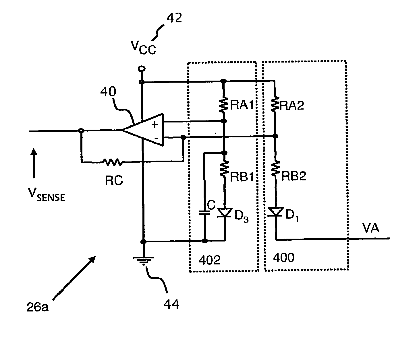
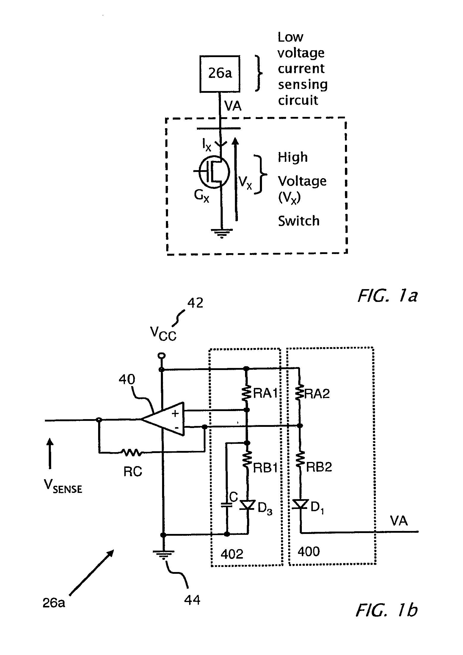
[0021]Reference is now made to FIG. 1a which is block diagram of high voltage switch GX connected to a current sensing circuit 26a, according to an embodiment of the present invention. High voltage switch GX is connected across a high voltage VX with respect to ground. A current sensing circuit 26a is connected to the high voltage side (VA) of switch GX. In an embodiment of the present invention, switch GX is a MOSFET. Alternatively switch GX can, in different embodiments of the invention, be a silicon controlled rectifier (SCR), insulated gate bipolar junction transistor (IGBT), bipolar junction transistor (BJT), field effect transistor (FET), junction field effect transi...


PUM


Abstract

A device having a switch with a voltage applied across the switch. A current sensing circuit is connected to one terminal of the switch. The current sensing circuit receives power independently of the voltage applied across the switch. The power supply shares the other terminal of the switch with the current sensing circuit. The switch is adapted for opening and closing. When the switch closes, the current sensing circuit senses current through the switch and upon opening the switch the high voltage of the switch is blocked from the current sensing circuit. The sense current is caused to flow from the current sensing circuit to the other terminal when the switch is closed. The flow of the sense current produces a voltage which is compared differentially to another voltage referenced by the other terminal

Description

CROSS REFERENCE TO RELATED APPLICATIONS[0001]The present invention benefits from U.S. application 60 / 992,589 filed 5 Dec. 2007 and is hereby incorporated by reference in its entirety.TECHNICAL FIELD[0002]The present invention relates to current sensing in electronic circuitry and specifically to a device and method for current sensing in a switching power converter.DESCRIPTION OF RELATED ART[0003]Reference is made to FIG. 1 which illustrates the conventional current sensing circuit of US 2008 / 0246460. US 2008 / 0246460 illustrates a conventional current sensing circuit 202 coupled to switching field-effect-transistors (FET) high side FET 210, and low side FET 206 within a switching regulator. The current-sensing-circuitry 202 is configured to bypass a small sense current 208 from the conducting current 209 of the switching-FET according to a sense ratio. The conducting current for the switching regulator is controlled by a control signal. Current sensing circuit 202 includes a sensing...

Claims


Application Information

Patent Timeline
IPC IPC(8): G01R19/00
CPCG01S3/7861H02J3/46H02M7/44Y02E10/58H02M7/493Y02E10/52H02J2300/26H02J3/381Y02E10/56H02M1/0077H02J3/388H02J3/38H02J13/00H02M1/0009H02S40/22H02M1/08H02M1/44H02M3/04
Inventor GAZIT, MEIR
Owner SOLAREDGE TECH LTD
Why Eureka
Try Eureka