
Method of reducing noise in a volume-rendered image

a volume-rendered image and noise reduction technology, applied in image enhancement, image analysis, instruments, etc., can solve the problems of noise obscuring all or a portion of the structure being imaged, difficult to create a 3d rendering without artifacts, and noise when imaging the ventricle of the hear

Inactive Publication Date: 2012-06-21
GENERAL ELECTRIC CO
View PDF4 Cites 31 Cited by
  • Summary
  • Abstract
  • Description
  • Claims
  • Application Information

AI Technical Summary

Benefits of technology

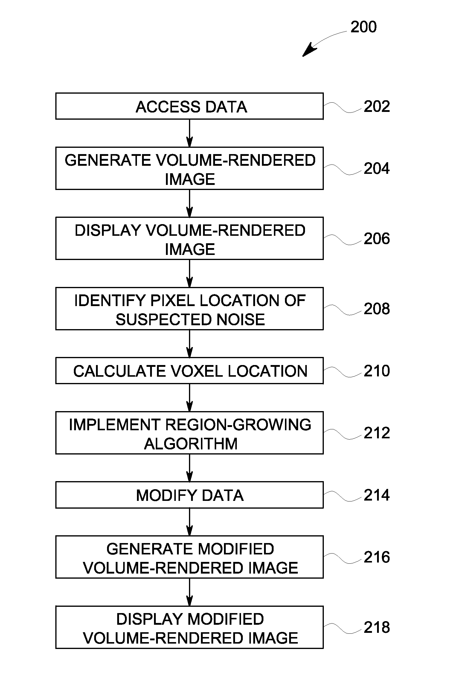
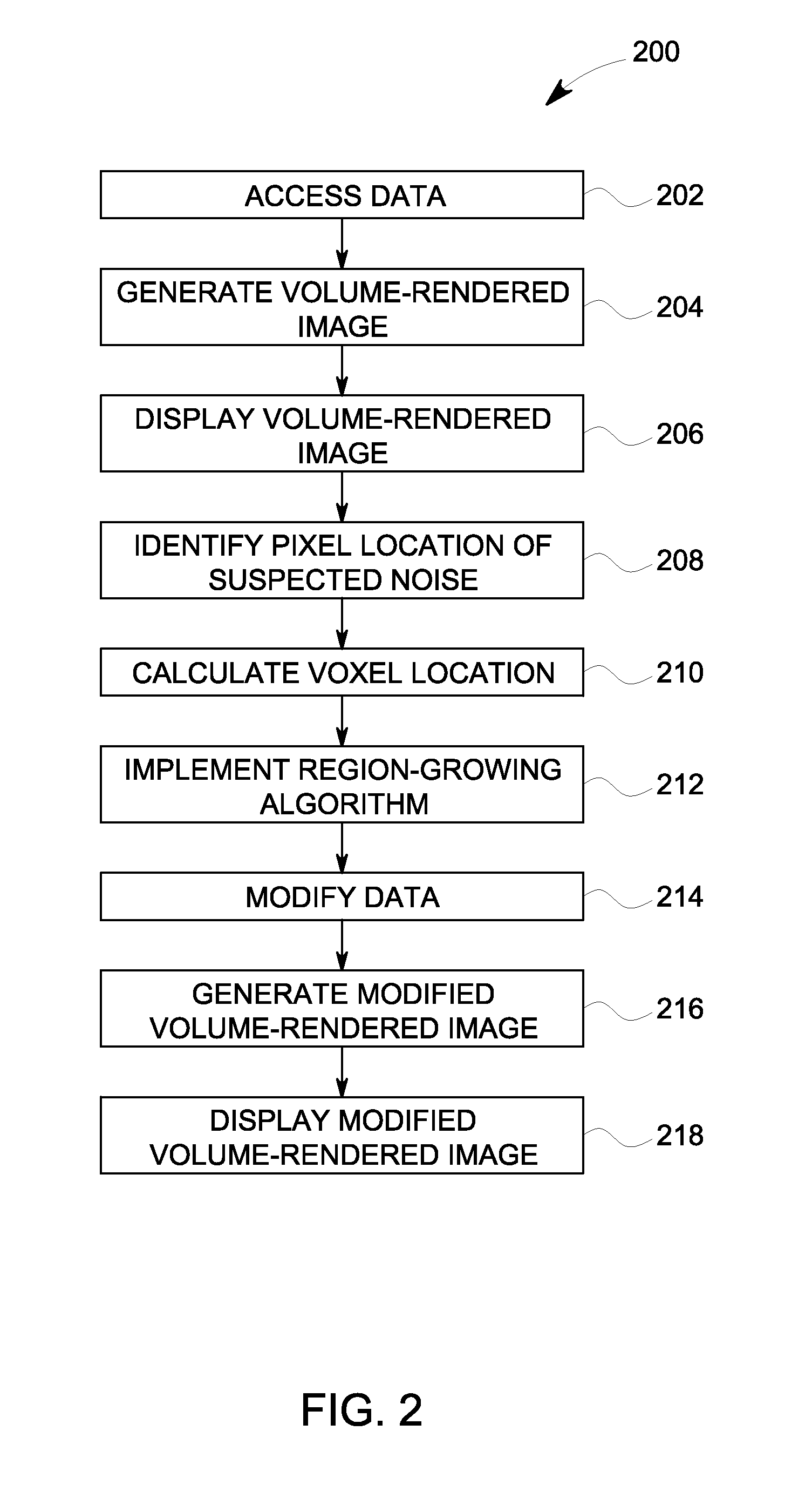
"The patent describes a method for reducing noise in a volume-rendered image. The method involves identifying a pixel location in the image that is suspected to have noise, and calculating a voxel location that intersects the surface of the image. The method then uses a region-growing algorithm to identify a plurality of voxels in the suspected noisy region. The data is then modified to assign lower opacity values to these voxels, resulting in a modified volume-rendered image with reduced noise. The technical effect of this method is improved image quality with reduced noise levels."

Problems solved by technology

Noise in a volume-rendered image may result when one or more voxels are incorrectly assigned a value that is not indicative of the anatomy being examined.
In ultrasound, acoustic noise such as reverberations may make it hard to create a 3D rendering without artifacts.
When viewing a volume-rendered image generated from 3D data, noise may obscure all or a portion of the structure being imaged.
For example, one frequent problem with volume-rendered ultrasound images is the presence of noise when imaging a ventricle of the heart.
The noise can make surfaces, such as the ventricle, difficult or impossible to visualize with standard rendering techniques like ray tracing.
Conventional techniques for dealing with noise in 3D datasets are largely manual and they require a large amount of user time in order to work satisfactorily.
The pixels of the volume-rendered image represent a weighted-sum of voxel opacity values and it can therefore be difficult to identify which pixels in the cut-planes correspond to noisy pixels in the volume rendered image.
All of the aforementioned steps add unnecessary time and complexity to each imaging procedure.
The process of reducing the noise in a volume-rendered image can be very burdensome to the operator, particularly when dealing with large datasets.

Method used


Image

  • Method of reducing noise in a volume-rendered image
  • Method of reducing noise in a volume-rendered image
  • Method of reducing noise in a volume-rendered image

Examples


Embodiment Construction

[0014]In the following detailed description, reference is made to the accompanying drawings that form a part hereof, and in which is shown by way of illustration specific embodiments that may be practiced. These embodiments are described in sufficient detail to enable those skilled in the art to practice the embodiments, and it is to be understood that other embodiments may be utilized and that logical, mechanical, electrical and other changes may be made without departing from the scope of the embodiments. The following detailed description is, therefore, not to be taken as limiting the scope of the invention.

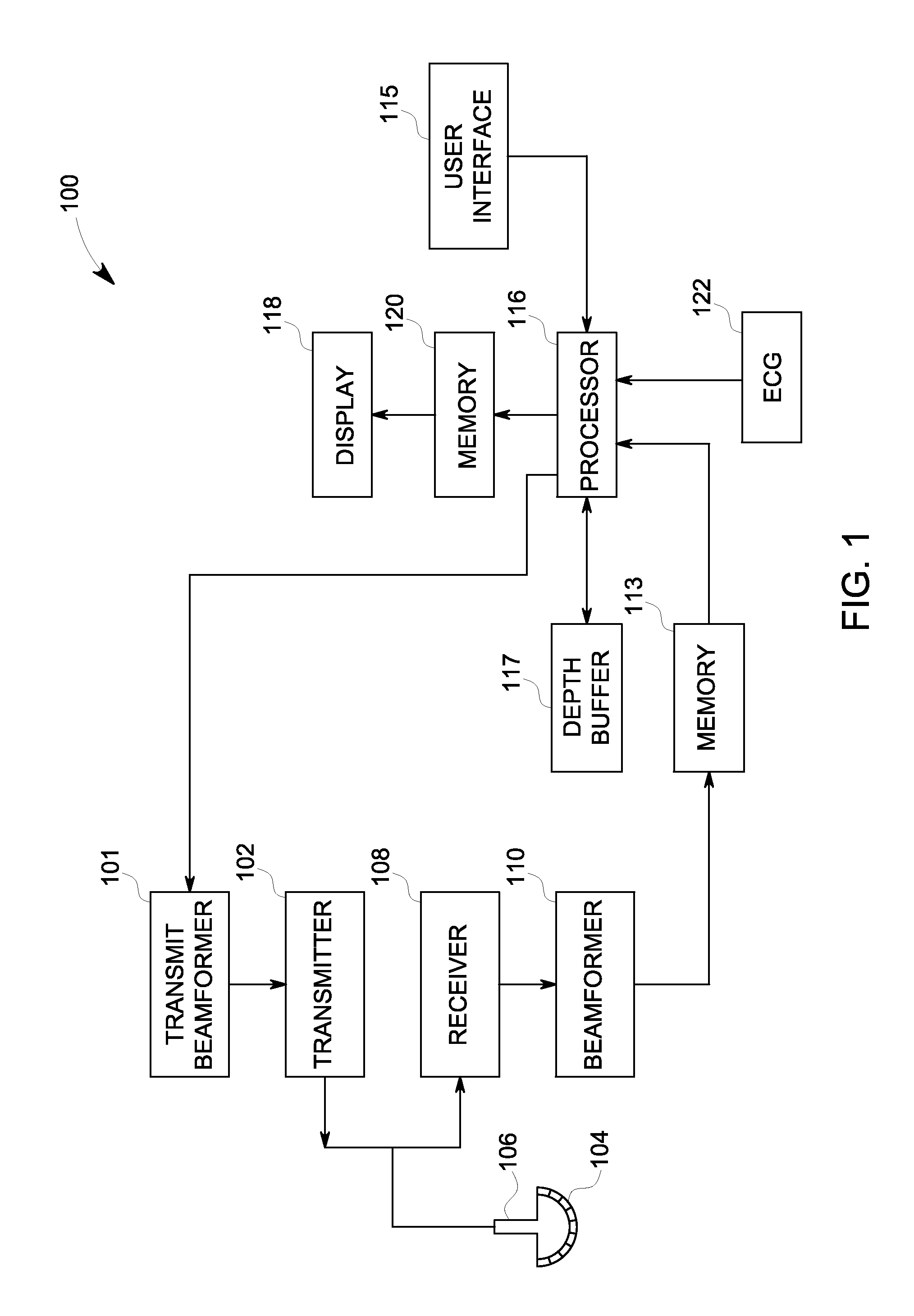
[0015]FIG. 1 is a schematic diagram of an ultrasound imaging system 100. The ultrasound imaging system 100 includes a transmit beamformer 101 and a transmitter 102 that drive transducer elements 104 within a probe 106 to emit pulsed ultrasonic signals into a body (not shown). A variety of geometries of probes and transducer elements may be used. The pulsed ultrasonic signals a...


PUM


Abstract

A method of reducing noise in a volume-rendered image includes generating a volume-rendered image from data, identifying a pixel location of suspected noise in the volume-rendered image, and calculating a voxel location that corresponds to the pixel location and intersects a rendered surface in voxel space. The method includes implementing a region-growing algorithm using the voxel location as a seed point to identify a plurality of voxels in a suspected noisy region. The method includes modifying the data to generate modified data by assigning lower opacity values to the plurality of voxels. The method includes generating a modified volume-rendered image from the modified data and displaying the modified volume-rendered image.

Description

FIELD OF THE INVENTION[0001]This disclosure relates generally to three-dimensional volume-rendered imaging and specifically to a technique for identifying and adjusting the opacity values of voxels in a suspected noisy region.BACKGROUND OF THE INVENTION[0002]A conventional volume-rendered image is typically a projection of three-dimensional (3D) data onto a two-dimensional (2D) viewing plane. Typically the volume-rendered image will be generated by a method such as ray tracing, which involves mapping a weighted sum of volume pixel elements, or voxels, along rays that originate from pixel locations in the viewing plane. Volume-rendered images are commonly used to view 3D medical imaging data. Typically, each of the voxels are assigned a value and a corresponding opacity value based on the information acquired by the medical imaging system. Commonly, the opacity value is a function of the voxel value. For example, the value of each voxel in computed tomography data typically represent...

Claims


Application Information

Patent Timeline
Patent Type & Authority Applications(United States)
IPC IPC(8): G06T17/00
CPCG06T15/08G06T2207/20141G06T7/0081G06T5/002G06T7/11G06T7/187G06T5/70
Inventor STEEN, ERIK NORMANN
Owner GENERAL ELECTRIC CO
Learn More