Light-emitting electronic textile with improved light diffusion

a technology of electronic textiles and light diffusion, applied in the field of light-emitting electronic textiles, can solve the problems of relatively large spacing between adjacent light sources and low resolution of current light-emitting electronic textiles, and achieve the effect of improving light-emitting electronic textiles

Inactive Publication Date: 2012-06-21
KONINKLIJKE PHILIPS ELECTRONICS NV
View PDF6 Cites 28 Cited by
  • Summary
  • Abstract
  • Description
  • Claims
  • Application Information

AI Technical Summary

Benefits of technology

[0007]In view of the above-mentioned and other drawbacks of the prior art, a general obj

Problems solved by technology

In general, currently available light-emitting electronic textiles have a rather low

Method used


Image

  • Light-emitting electronic textile with improved light diffusion
  • Light-emitting electronic textile with improved light diffusion
  • Light-emitting electronic textile with improved light diffusion

Examples


Embodiment Construction

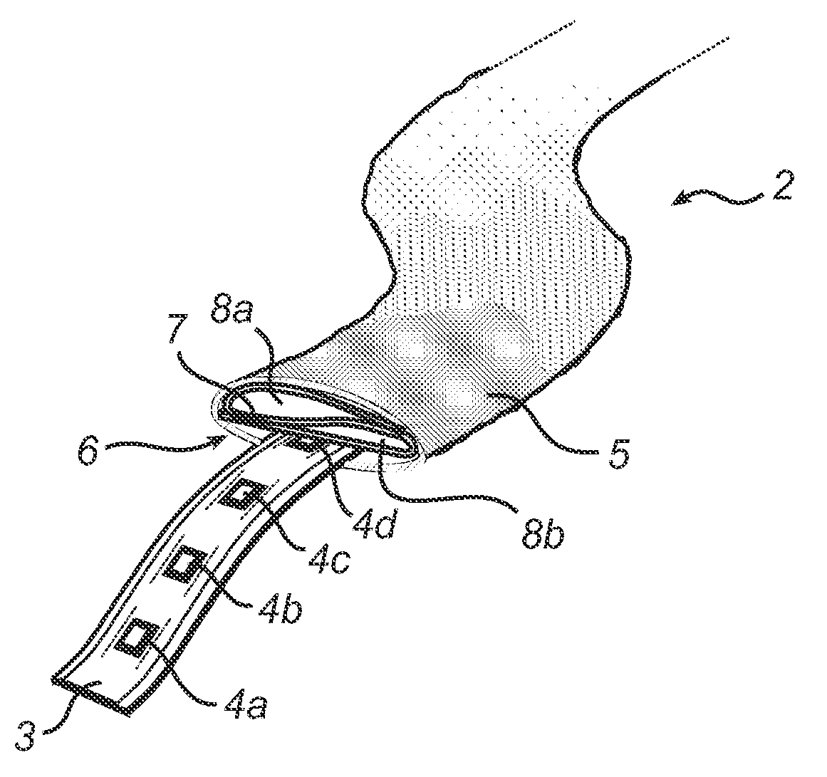
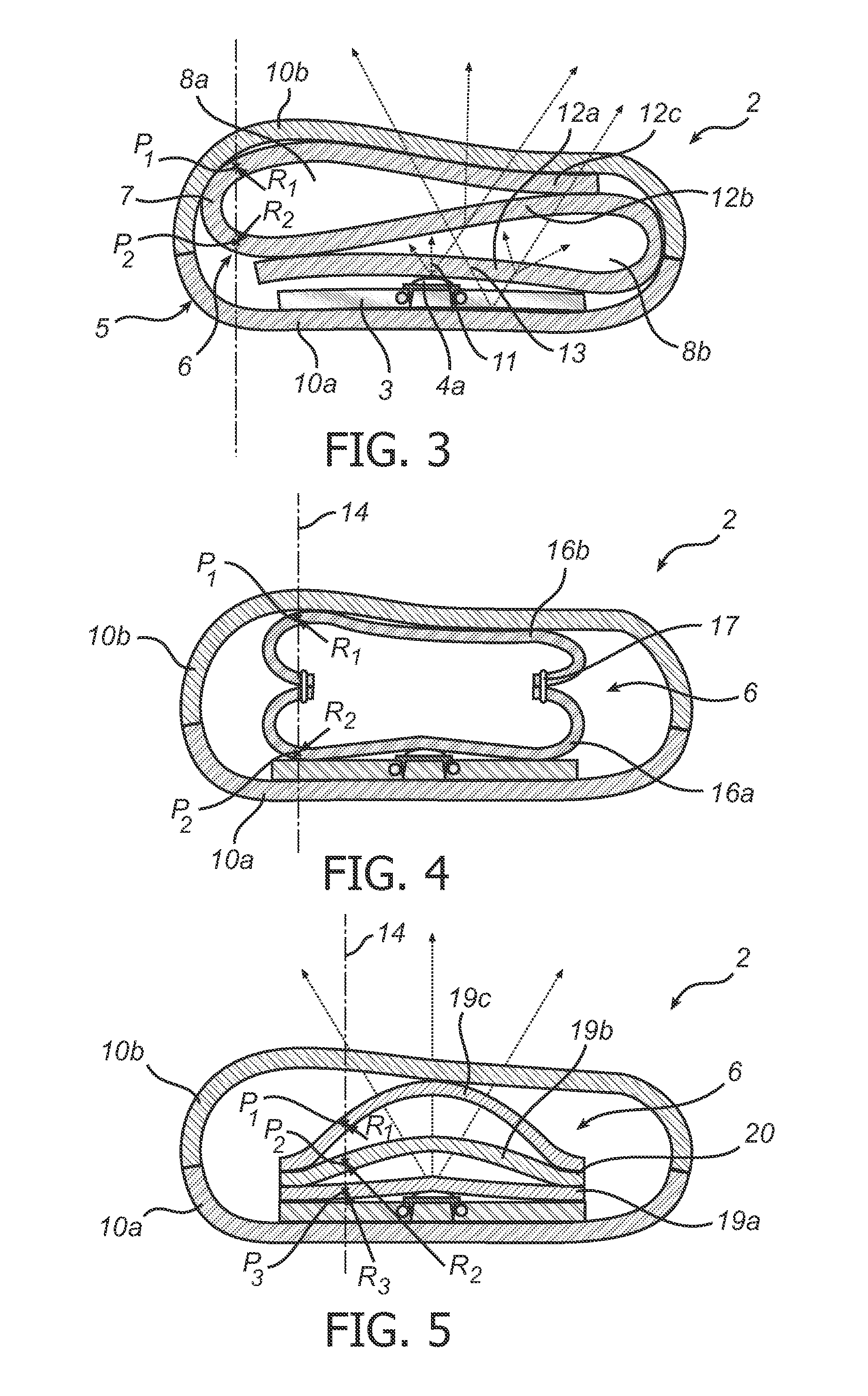
[0038]In the following description, the present invention is described with reference to a light-emitting electronic textile in which the light-diffusing member is formed by one or several sheets of a non-woven textile material enclosed by tubular cover textile.

[0039]It should be noted that this by no means limits the scope of the invention, which is equally applicable to other light-emitting electronic textiles in which the cover textile is differently provided, for example as a one-sided cover being attached to the flexible component carrier. Furthermore, the light-diffusing member can be formed by a layered structure in any other suitable layered configuration formed by a plurality of light-diffusing layers, such as woven textile layers, foam layers or layers of different light-diffusing materials suitable for use in a light-emitting electronic textile.

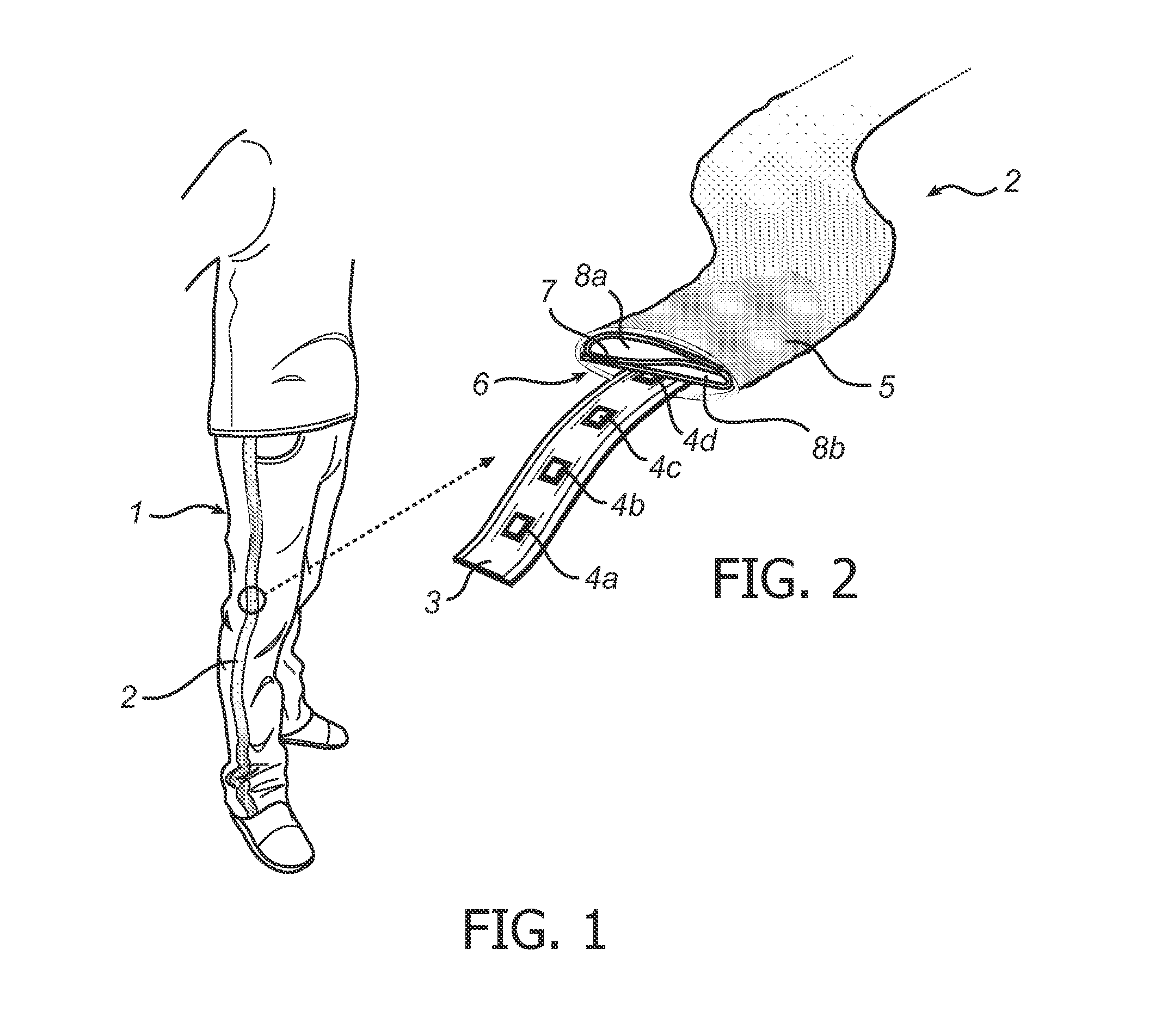
[0040]FIG. 1 schematically illustrates an exemplary application for various embodiments of the light-emitting electronic textile ...


PUM

PropertyMeasurementUnit
Thicknessaaaaaaaaaa
Flexibilityaaaaaaaaaa
Radiusaaaaaaaaaa

Abstract

A light-emitting electronic textile (2) comprising a flexible component carrier (3) having a plurality of light-sources (4a-c) arranged thereon; a cover textile (5) arranged to allow passage through the cover textile (5) of light emitted by the light-sources (4a-c); and a light-diffusing member (6) arranged between the light-sources (4a-c) and the cover textile (5). The light-diffusing member (6) comprises a layered structure formed by a plurality of light-diffusing layers (12a-c; 16a-b; 19a-c), wherein adjacent light-diffusing layers in the layered structure are spaced apart at least in portions of the light-diffusing member (6) corresponding to positions of the light-sources (4a-c).

Description

FIELD OF THE INVENTION[0001]The present invention relates to a light-emitting electronic textile and to a method for manufacturing such a light-emitting electronic textile.BACKGROUND OF THE INVENTION[0002]By integrating light-sources, such as light-emitting diodes (LEDs), into textile applications and thereby creating light-emitting electronic textiles, attractive visual effects can be achieved.[0003]In general, currently available light-emitting electronic textiles have a rather low resolution, that is, the spacing between adjacent light-sources is relatively large. Furthermore, it has been found that end users often prefer that the light-emitting electronic textile gives the impression that the light-sources are not isolated spots of light.[0004]For this reason, currently proposed light-emitting electronic textiles may be provided with a diffusing element arranged on top of the light-sources to achieve a more uniform output of light from the light-emitting electronic textile.[0005...

Claims


Application Information

Patent Timeline
IPC IPC(8): F21V21/08H05K13/00
CPCG09F23/04F21Y2101/02Y10T29/49002A41D27/085G09F21/02F21V33/0008G09F13/22F21Y2115/10
Inventor UBAGHS, GUY WILHELMUS MARIEBHATTACHARYA, RABIN
Owner KONINKLIJKE PHILIPS ELECTRONICS NV
Why Eureka
Try Eureka