LED light emitting group

a technology of led light and light-emitting components, which is applied in the direction of semiconductor devices for light sources, lighting and heating apparatus, lighting support devices, etc., can solve the problems of not allowing the same lighting effect, high cost, and low intensity of LED light-emitting components

Inactive Publication Date: 2012-06-21
KONINKLIJKE PHILIPS ELECTRONICS NV +1
View PDF10 Cites 16 Cited by
  • Summary
  • Abstract
  • Description
  • Claims
  • Application Information

AI Technical Summary

Benefits of technology

[0007]An additional object of the present invention, then, is to implement an emitting group which can be adap

Problems solved by technology

However, the known light sources, in turn, even if they solve different problems characteristic of the above-mentioned lamps, suffer from the drawback of emitting light beams, the light intensity thereof is much lower than that of the emitting groups fed with low voltage, and for this reason they do not allow obtaining the same lighting effect.
The known emitting groups using LED sources, then, particularly complex from an implementing point of view and with high costs above all due to the fact that they include

Method used


Image

  • LED light emitting group
  • LED light emitting group
  • LED light emitting group

Examples


Embodiment Construction

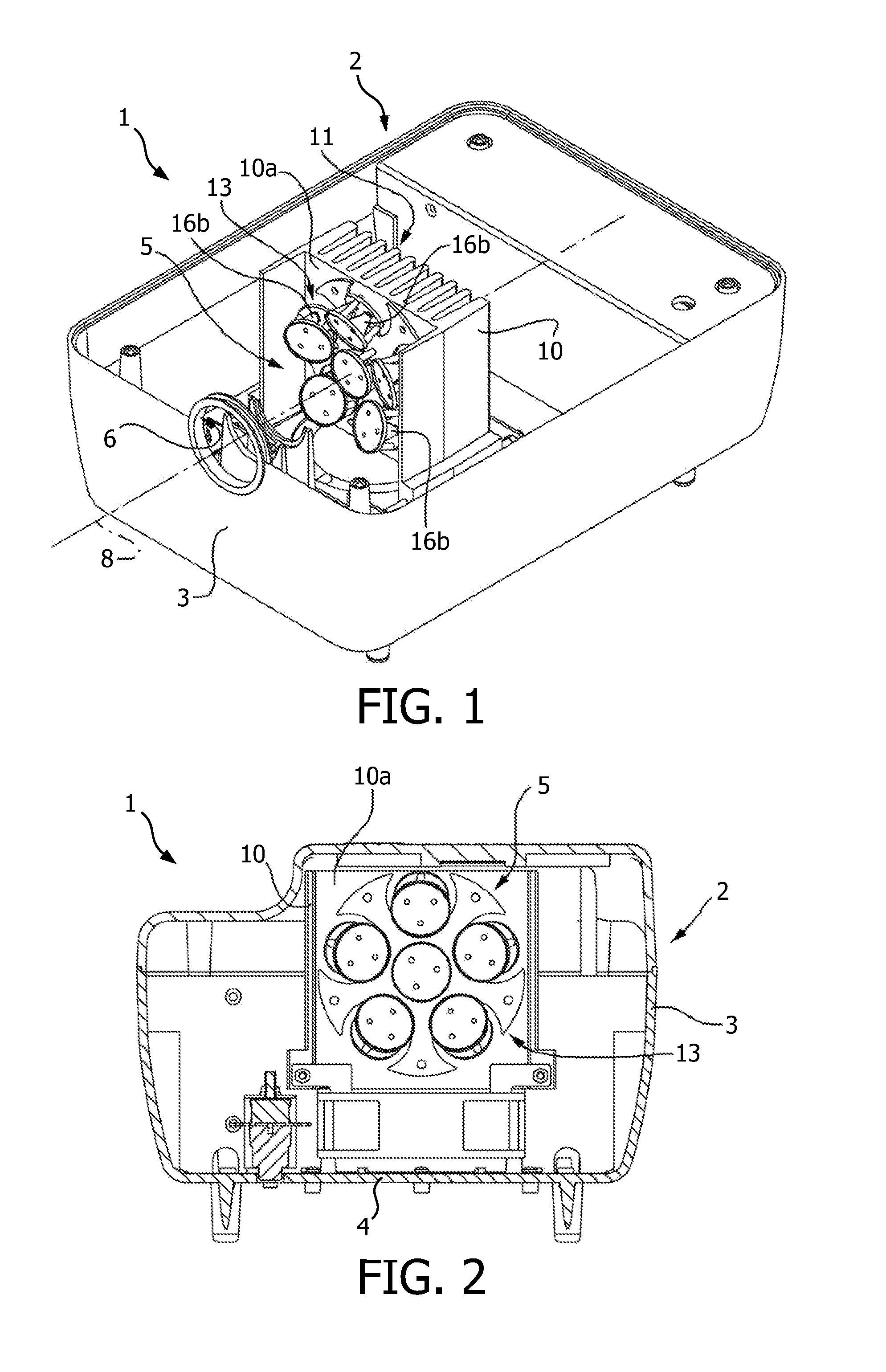
[0017]In FIGS. 1 and 2, a LED light emitting group is designated as a whole by reference number 1, comprising an outer casing 2, which has a side wall 3 and a bottom wall 4 and it houses a light source 5 and is apt to emit, through an opening 6 of the side wall 3, an outgoing light beam having its own optical axis 8.

[0018]The light source 5 comprises a coupling wall 10 which, in the described particular example, extends upwards from the bottom wall 4 of the casing 2 in position faced to the opening 6 and orthogonal to the optical axis 8 and it is equipped on the rear side with a finned heat sink, designated with reference number 11.

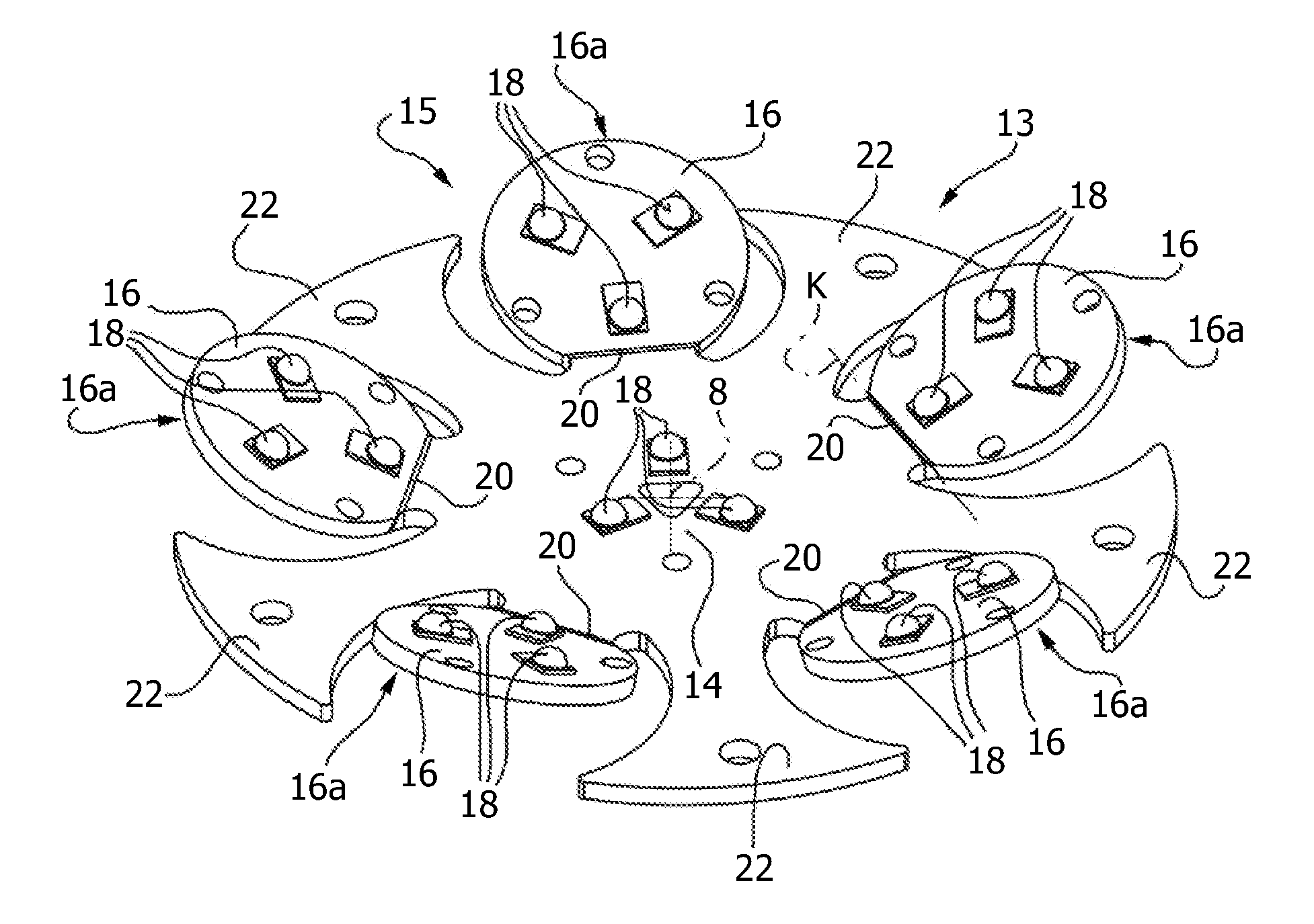
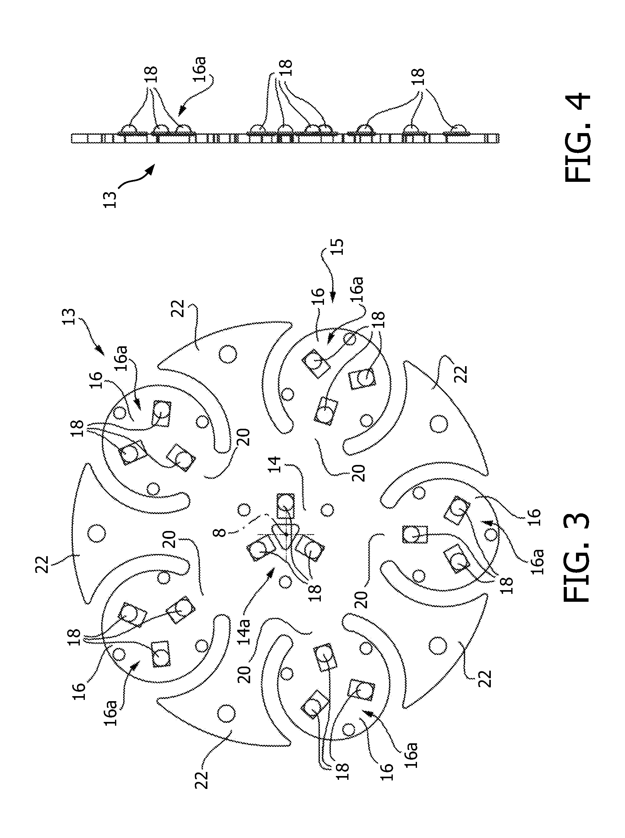
[0019]Still with reference to FIGS. 1 and 2, the light source 5 further comprises a multiflap body 13, which is implemented as a single piece starting from a plane disk made of metallic material (FIGS. 3 and 4) and it is fixedly connected to a surface 10a of the coupling wall 10 faced to the opening 6. According to what illustrated in FIGS. 3 to 6, the mu...


PUM


Abstract

A LED light emitting group (1) apt to produce an outgoing light beam having its own optical axis (8) is equipped with a plurality of LEDs (18), distributed on a plate-shaped body (13) and having a fixed central plane portion (14) orthogonal to the optical axis (8) and a crown (13) of peripheral plane portions (16) tilted with respect to the central plane portion (14) and converging the one towards the other one and towards the central plane portion (14) and the optical axis (8); each one of said plane portions (14, 16) carrying a plurality of said LEDs (18).

Description

FIELD OF THE INVENTION[0001]The present invention relates to a LED light emitting group.BACKGROUND OF THE INVENTION[0002]In the field of lighting in general it is known utilizing different typologies of light emitting groups, which differ the ones from the other ones above all in the type of the used light sources. More in detail, as light source, it is known using halogen lamps, filament lamps or lamps with metallic iodides fed with low voltage (usually between fifty and three hundred eighty volts) or light emitting diodes, commonly known as LEDs and fed with very low voltage.[0003]However, the known light sources, in turn, even if they solve different problems characteristic of the above-mentioned lamps, suffer from the drawback of emitting light beams, the light intensity thereof is much lower than that of the emitting groups fed with low voltage, and for this reason they do not allow obtaining the same lighting effect.[0004]The known emitting groups using LED sources, then, part...

Claims


Application Information

Patent Timeline
IPC IPC(8): F21V21/14F21V21/00
CPCF21K9/00F21V19/02F21Y2105/001F21S2/005F21Y2101/02F21V14/02F21Y2105/10F21K9/65F21Y2115/10F21Y2107/80
Inventor SPACCASASSI, CLAUDIOALBANO, CARLO
Owner KONINKLIJKE PHILIPS ELECTRONICS NV
Why Eureka
Try Eureka