Image sensing device, image sensing device control method, and program for the control method

Inactive Publication Date: 2012-06-21
HITACHI INFORMATION & CONTROL SOLUTIONS LTD
View PDF6 Cites 6 Cited by
  • Summary
  • Abstract
  • Description
  • Claims
  • Application Information

AI Technical Summary

Benefits of technology

[0015]However, in the case of the technique disclosed in JP 2005-62665 A, a target object distance is set at the focus-lens position where the target object is in focus by the auto-focus control and then the auto-focus control is switched to the manual-focus control. Thus, there has been an out-of-focus problem which is caused, for example as shown in FIG. 4, when the auto-focus control is performed on the wide-side having a lower focus-driving resolution, and subsequently the manual-focus-trace control is performed on the tele-side having a greater focus-driving resolution, at the target object distance which has been set,
[0016]On the other hand, the technique disclosed in JP 2006-215285 A is not preferable in consideration of the life of driving the focus-lens, since the manual control is turned on only if the zoom-lens is traveled and the auto-focus control is constantly performed. Furthermore, the technique disclosed in JP 2006-215285 A has the identical problem as that in the technique disclosed in JP 2005-62665 A, when the auto-focus control is enabled in the wide-side. In addition, when the auto-focus control is disabled on the wide-side, the auto-focus control is not performed on the wide-side, thus, the focus-lens position is not always optimized, and consequently a deterioration problem of the focusing precision is caused.
[0017]In the technique disclosed in JP H11-281869 A, there has been a problem that the user cannot arbitrarily set a target object distance depending on the target object during the zoom-lens operation, since the focus-lens position, during the zoom-lens operation, is fixed to a pre-determined target object distance such as the infinity or the like for the control purpose.
[0018]Therefore, the present invention is made in consideration of the aforementioned problems, and an object of the present invention is to provide an image sensing device, an i

Problems solved by technology

Thus, there has been an out-of-focus problem which is caused, for example as shown in FIG. 4, when the auto-focus control is performed on the wide-side having a lower focus-driving resolution, and subsequently the manual-focus-trace control is performed on the tele-side having a greater focus-driving resolution, at the target object distance which has been set,
Furthermore, the technique disclosed in JP 2006-215285 A has the identical problem as that in the technique disclosed in JP 2005-62665 A, when the auto-focus control is enabled in the wide-side.
In addition, when the auto-focus con

Method used


Image

  • Image sensing device, image sensing device control method, and program for the control method
  • Image sensing device, image sensing device control method, and program for the control method
  • Image sensing device, image sensing device control method, and program for the control method

Examples


Example

[0025]Hereinafter, an embodiment of the present invention is described with reference to the accompanying drawings.

1>

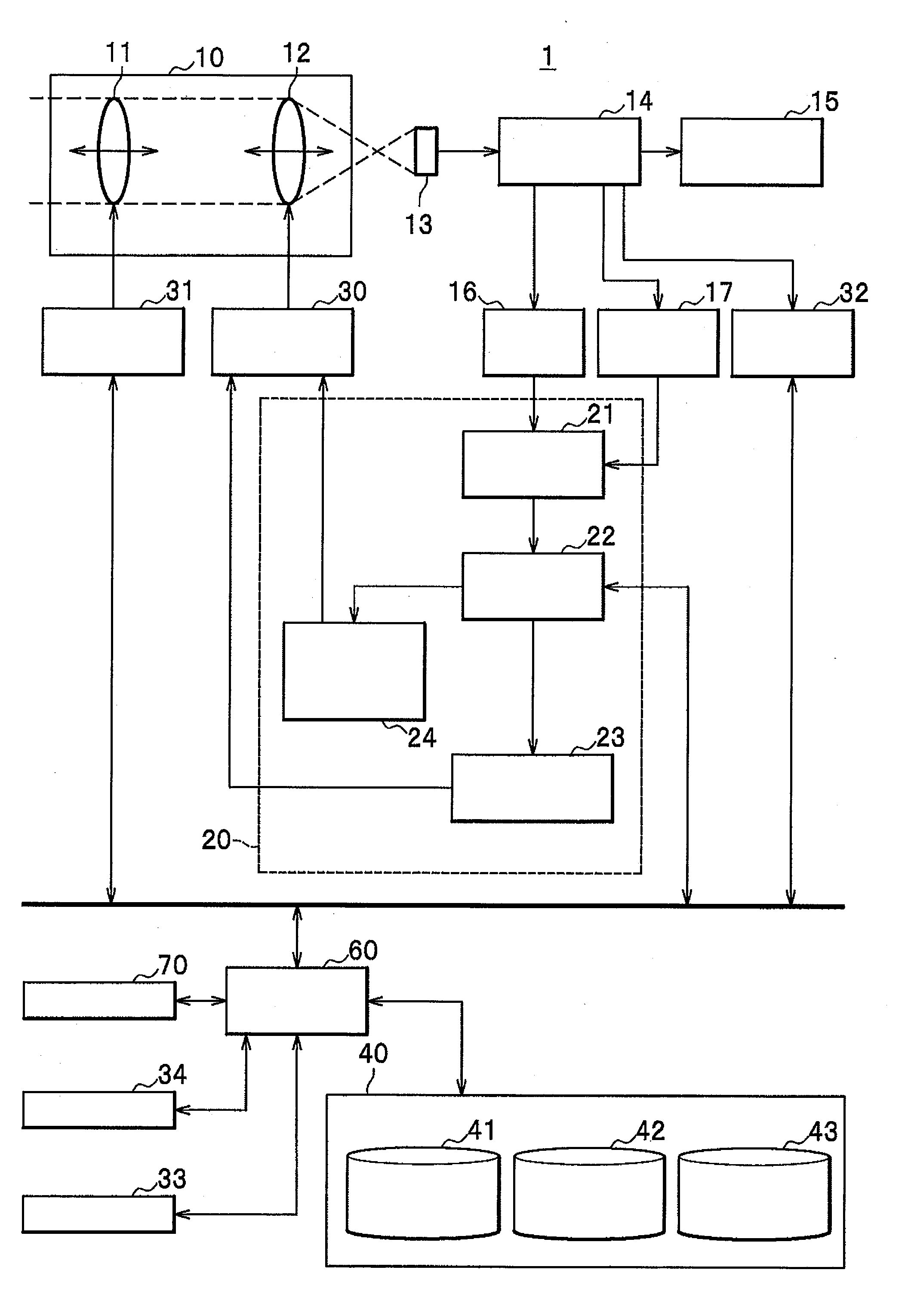
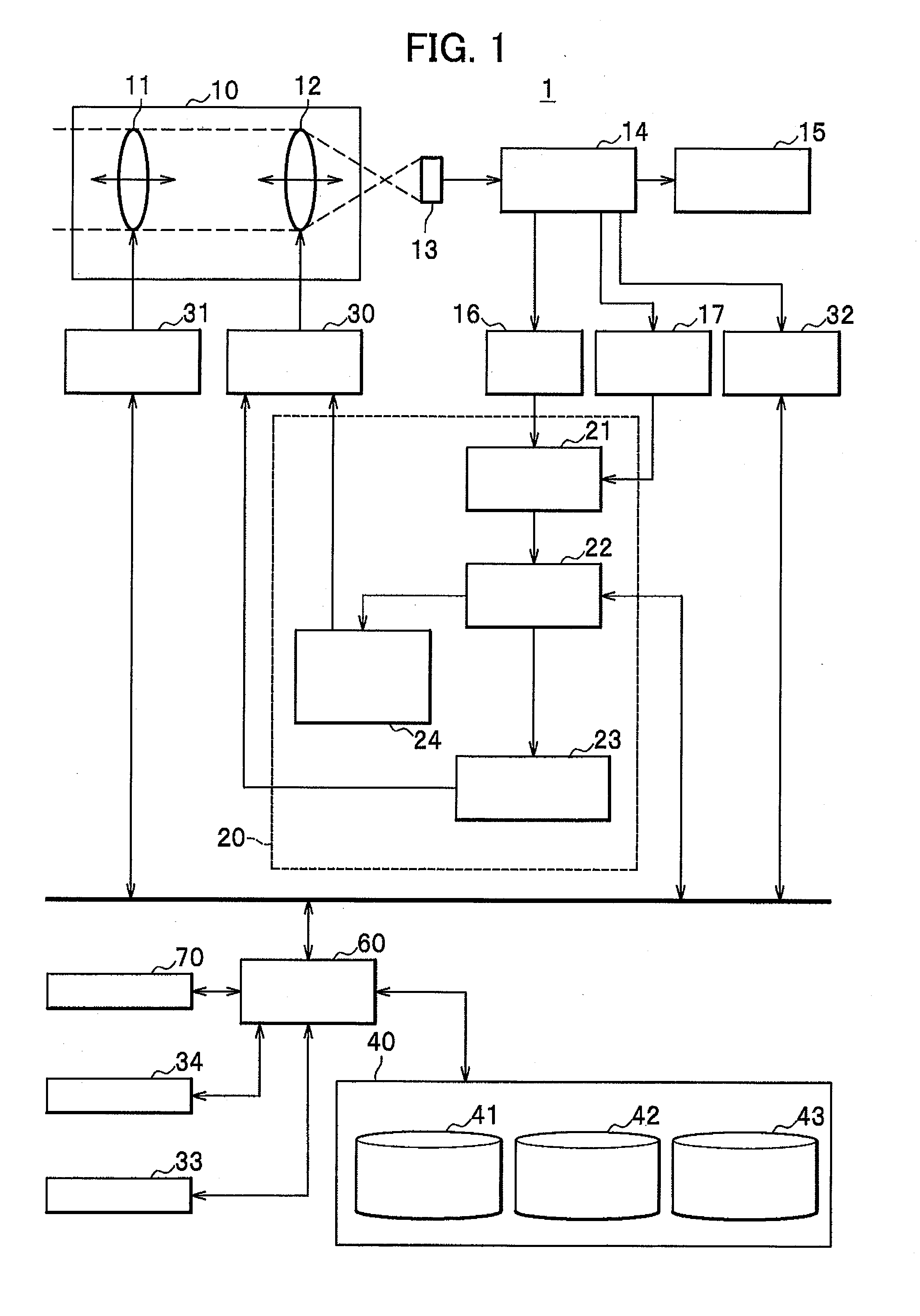
[0026]As shown in FIG. 1, the image sensing device 1 comprises an optical system 10, an image pick-up element 13, a camera control section 14, a display section 15, a focus signal generation section 16, a screen intensity evaluation detection section 17, a focus control section 20, a focus-lens drive section 30, a zoom-lens drive section 31, an illuminance control section 32, a temperature detection section 33, a time measurement section 34, a storage section 40, a system control section 60, and a command section 70.

[0027]In this embodiment, a surveillance camera is explained as an example of the image sensing device 1. The command section 70 is provided in order to manipulate the surveillance camera for the user located away from the surveillance camera.

[0028]A target object being shot is formed into an optical image on the light sensing surface of the image pick-up ...


PUM


Abstract

For preventing frequent use of auto-focus control and also for acquiring stable in-focus positions for target-objects, this invention comprises system control section 60 having a second mode to drive magnification adjustment lens 11 or focus adjustment lens 12 upon a user command, and a third mode to transition to a first mode under pre-determined conditions in the second mode, and to set in-focus states of a lens group, wherein system control section 60 stores a reference target-object distance in reference target-object distance storage section 43 when focus adjustment lens 12 is driven by user commands in the second mode, drives focus adjustment lens 12 not based on a current target-object distance but the lens in-focus trajectory data to retain the reference target-object distance when the magnification adjustment lens 11 is driven by user commands, and re-transitions to the second mode without updating the reference target-object distance, after the third mode.

Description

CROSS REFERENCE TO RELATED APPLICATION[0001]This application claims priority under 35 U.S.C. §119 to Japanese Patent Application No. 2010-281444 filed on Dec. 17, 2010, the disclosure of which is incorporated herein by reference.BACKGROUND OF THE INVENTION[0002]1. Field of the Invention[0003]The present invention relates to an image sensing device, more particularly, to an image sensing device which is capable of switching an auto-focus control and a manual control.[0004]2. Description of the Related Art[0005]In image sensing devices such as surveillance cameras, video cameras, or the like, the auto-focus control and the manual control are extensively utilized. Further, the manual control includes two types which are a manual-focus control and a manual-focus-trace control. Incidentally, in this specification, the auto-focus control is denoted by a first mode, and the manual control is denoted by a second mode.[0006]The auto-focus control is a control for performing focus adjustment ...

Claims


Application Information

Patent Timeline
IPC IPC(8): G02B7/09
CPCG02B7/28H04N5/23212G03B13/36H04N23/675
Inventor ANDO, AKIRAYOKOYAMA, TOSHIYUKINISHIGUCHI, TOMOAKI
Owner HITACHI INFORMATION & CONTROL SOLUTIONS LTD
Why Eureka
Try Eureka