
Artificial Sphincter System and Method

a technology of artificial sphincter and sphincter, which is applied in the field of pelvic disorders, can solve the problems of inefficiency associated with imprecise manual pump volume, patient self-conscious or conspicuous in public, and severe limitations on patient's activities

Active Publication Date: 2012-06-21
BOSTON SCI SCIMED INC
View PDF11 Cites 42 Cited by
  • Summary
  • Abstract
  • Description
  • Claims
  • Application Information

AI Technical Summary

Benefits of technology

The present invention is an artificial sphincter that uses an electro-mechanical pump system to control continence. It includes an inflatable cuff, a control pump, and an electro-mechanical pump actuator. The inflatable cuff can be inflated or deflated to control the patient's bladder or rectum. The artificial sphincter can be controlled using sensors, electronic control devices, and remote actuation devices. The invention also includes a chamber system for the pump, which can displace fluid to inflate or deflate the cuff. Other embodiments include a peristaltic or roller pump system, a squiggle pump system, or a centrifugal or vane pump system to control fluid flow and distribution. The technical effects of the invention include improved control and efficiency of the artificial sphincter system for patients with bladder or rectal control issues.

Problems solved by technology

As one might expect, this condition can be quite debilitating and embarrassing and may severely limit the patient's activities.
The process may be considered burdensome and cause the patient to feel self conscious or conspicuous in public.
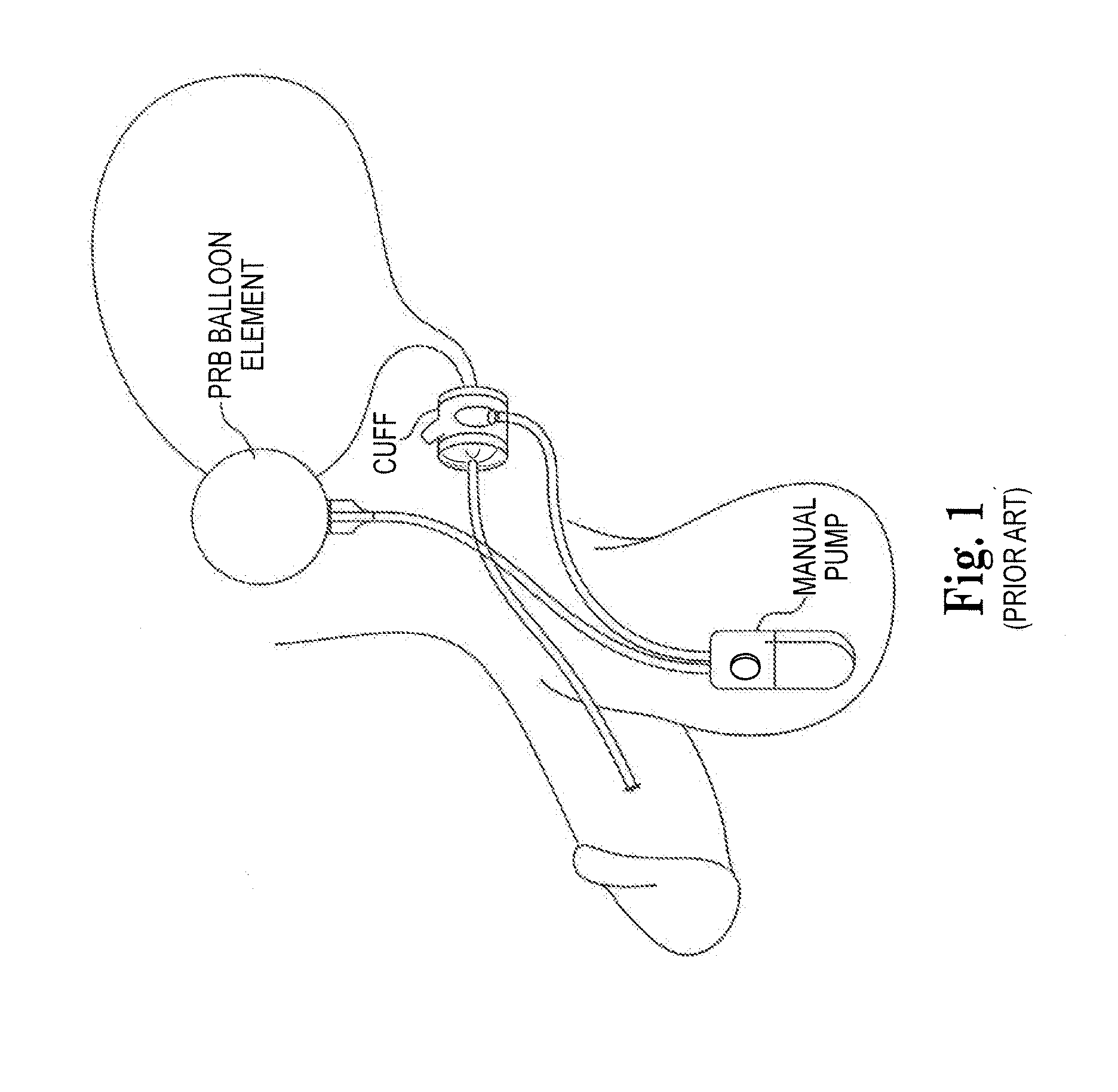
In addition, there may be issues with over-pumping, as well as inefficiencies associated with imprecise manual pump volumes.
Further, it is possible that urethral tissue health can be compromised by continuous cuff pressure.

Method used


Image

  • Artificial Sphincter System and Method
  • Artificial Sphincter System and Method
  • Artificial Sphincter System and Method

Examples


Embodiment Construction

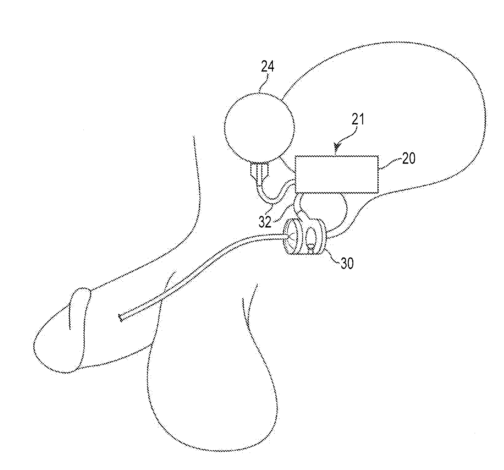
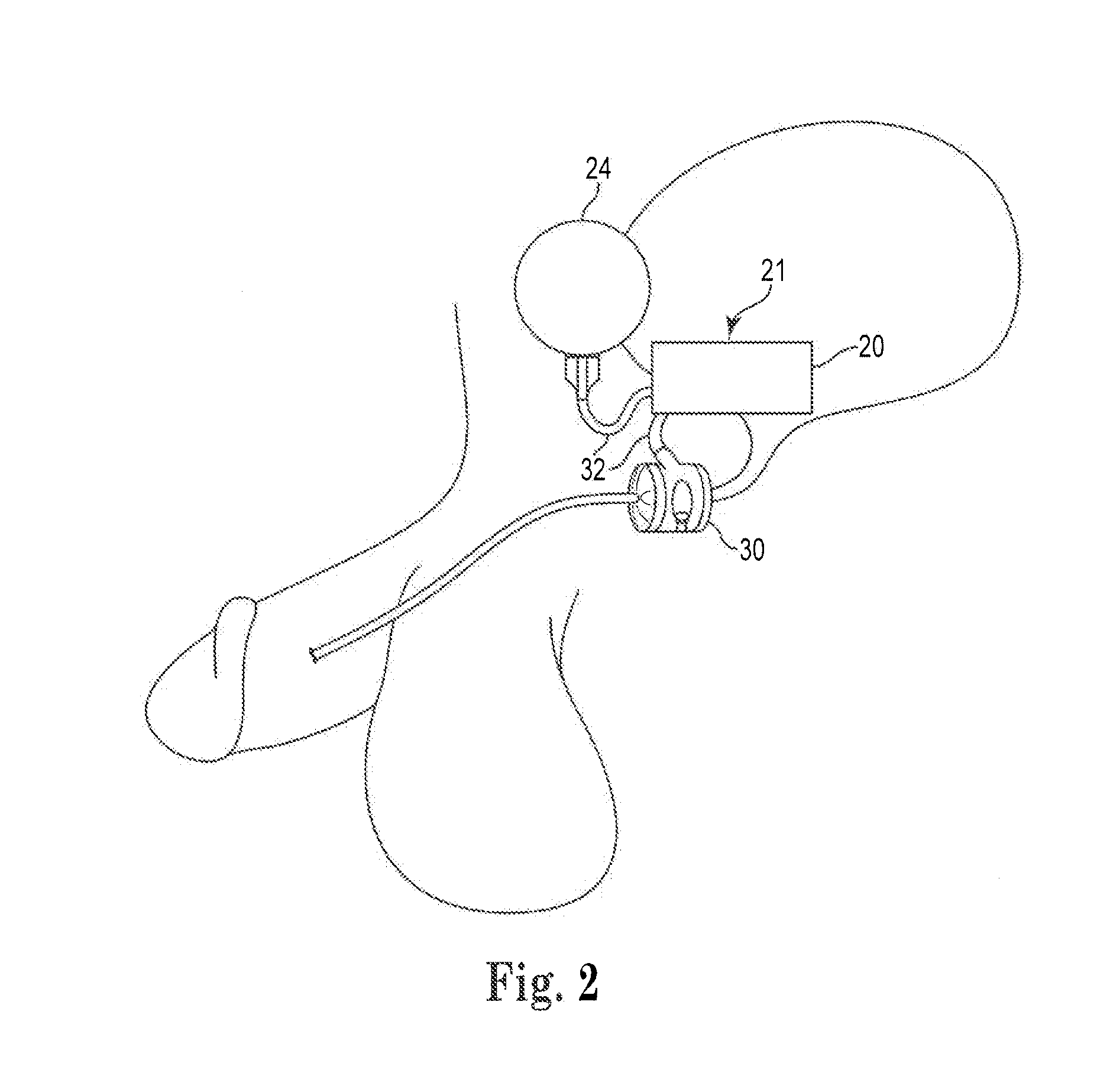
[0019]Referring generally to FIGS. 2-33, embodiments of the present invention can include an artificial sphincter system 10 adapted to control incontinence in the patient. In general, the cuff is attached to or wraps around a portion of the patient's urethra (or rectum) to control the sphinctering function of the particular anatomy.

[0020]The artificial urinary sphincter (“AUS”) system 10 includes an electro-mechanical control pump 20 attached to a pressure-regulating inflation balloon or element 24. The inflation element 24 is likewise in operative fluid communication with the cuff 30 via one or more tubes or conduits 32, chambers, valves or similar structures. The various conduits 32 can be separable at connectors to facilitate the implantation during a surgical procedure. The inflation element 24 is constructed of polymer material that is capable of elastic deformation to reduce fluid volume within the inflation element 24 and push fluid out of the element 24 and into the cuff 30....


PUM


Abstract

The present invention provides an artificial sphincter employing an easily controlled electro-mechanical pump system. The artificial sphincter includes an inflatable cuff, a control pump fluidly coupled to the inflatable cuff, and an electro-mechanical pump system. The inflatable cuff is adapted to surround a urethra or rectum of the patient to facilitate continence. An inflation element or balloon can be included to further control pressure to the cuff.

Description

PRIORITY[0001]This application claims priority to and the benefit of U.S. Provisional Patent Application No. 61 / 423,777, filed Dec. 16, 2010 and entitled “Artificial Sphincter System and Method,” which is hereby incorporated by reference in its entirety.FIELD OF THE INVENTION[0002]The present invention relates generally to treatment of pelvic disorders and, more particularly, to an electro-mechanical artificial urinary sphincter system activated by a remote control, implanted switch or like device.BACKGROUND OF THE INVENTION[0003]Incontinence is an affliction that prevents a patient from controlling waste elimination functions. As one might expect, this condition can be quite debilitating and embarrassing and may severely limit the patient's activities.[0004]Various techniques exist for treating incontinence in patients. One such technique is surgical implantation of an artificial sphincter. One form of artificial sphincter includes an appropriately sized inflatable cuff that is pos...

Claims


Application Information

Patent Timeline
Patent Type & Authority Applications(United States)
IPC IPC(8): A61F2/04
CPCA61F2/004
Inventor WIRBISKY, ALAN G.VANDEWEGHE, ANDREW P.
Owner BOSTON SCI SCIMED INC
Learn More