
Methods and apparatus for forwarding-state transport in a distributed control plane

a technology of forwarding state and control plane, applied in the field of control plane, can solve the problems of cumbersomeness, large and unmanageable centralized control plane, network system, etc., and achieve the effect of reducing and increasing the number of control planes

Active Publication Date: 2012-06-21
JUMIPER NETWORKS INC
View PDF2 Cites 63 Cited by
  • Summary
  • Abstract
  • Description
  • Claims
  • Application Information

AI Technical Summary

Benefits of technology

[0005]In some embodiments, a system includes a first network control entity, a second network control entity and a third network control entity. The first network control entity and the second network control entity are associated with a first network segment. The third network control entity is associated with a second network segment. The first network control entity is operable to send to the second network control entity an identifier of the first network segment and forwarding-state information associated with a data port at a first network element. The second network control entity is operable to receive the identifier of the first network segment and the forwarding-state information. The second network control entity is operable to send the forwarding-state information to a second network element. The first network control entity does not send the identifier of the first network segment and the forwarding-state information to the third network control entity.

Problems solved by technology

Such a centralized control plane, however, can become extremely large and unmanageable when a large number of resources are connected to the networking system.
Such known networking systems, however, are not suitable for large scale networking systems having a large number of nodes implementing a portion of the control plane.
This can become cumbersome when frequent updates are made to a large scale networking system.

Method used


Image

  • Methods and apparatus for forwarding-state transport in a distributed control plane
  • Methods and apparatus for forwarding-state transport in a distributed control plane
  • Methods and apparatus for forwarding-state transport in a distributed control plane

Examples


Embodiment Construction

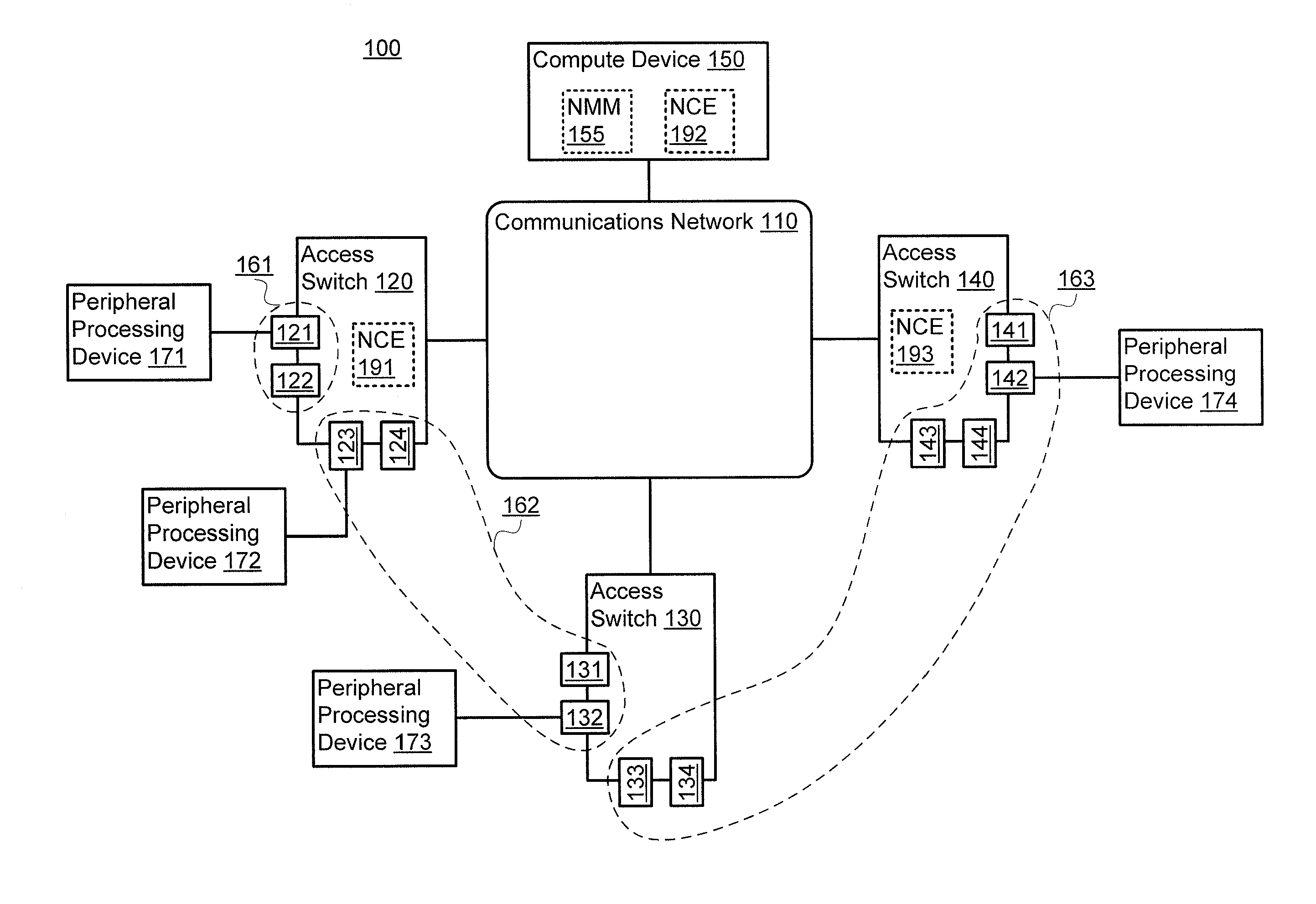
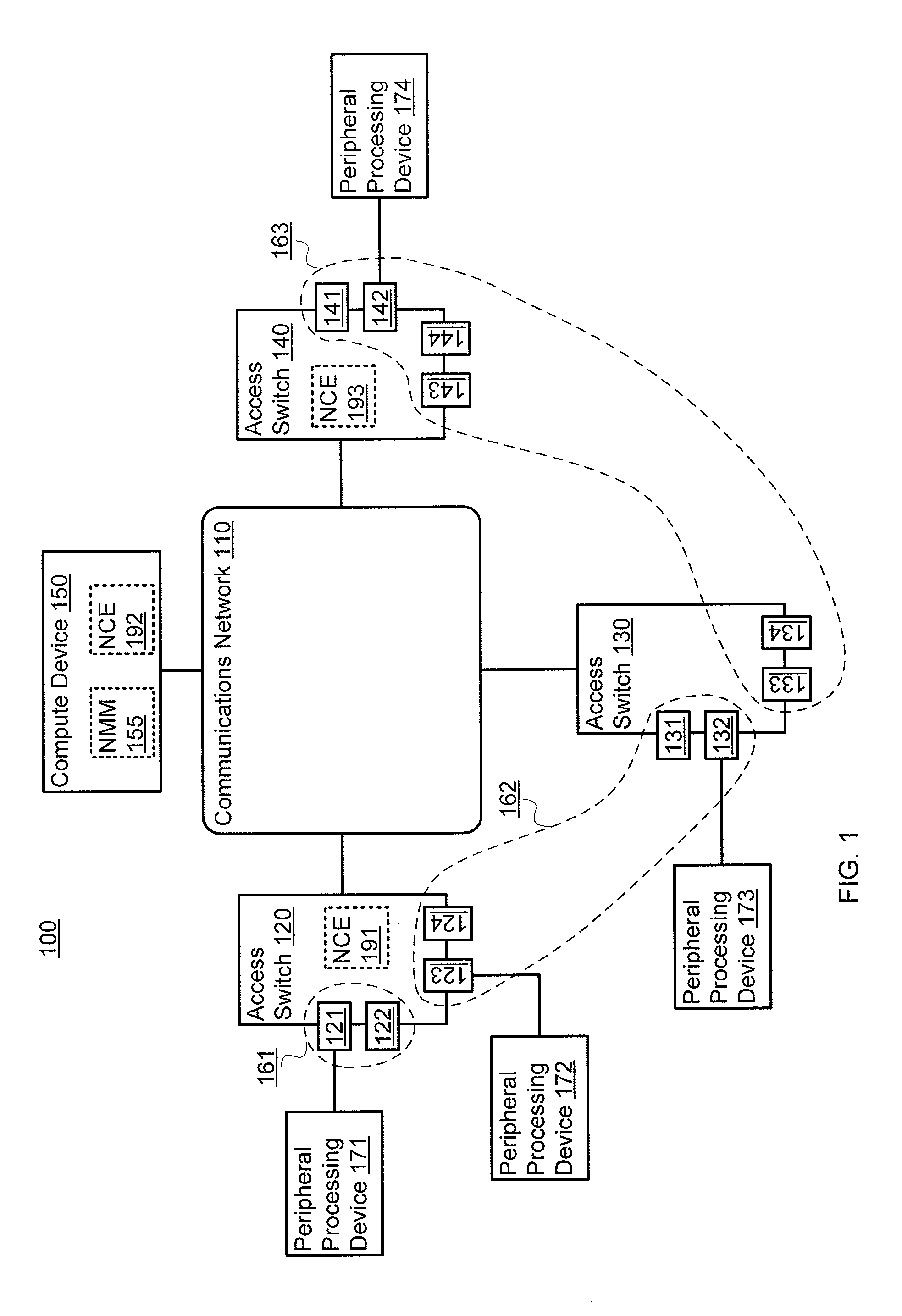
[0013]In some embodiments, a system includes a first network control entity, a second network control entity and a third network control entity. The first network control entity is associated with a first network segment including at least a portion of a set of data ports at a first network element operatively coupled to a data plane of a switch fabric. The second network control entity is associated with the first network segment including at least a portion of a set of data ports at a second network element operatively coupled to the data plane of the switch fabric. The third network control entity is associated with a second network segment including at least a portion of the set of data ports at a third network element operatively coupled to the data plane of the switch fabric. The first network control entity is operable to send to the second network control entity an identifier of the first network segment and forwarding-state information associated with a data port from the p...


PUM


Abstract

In some embodiments, a system includes a first network control entity, a second network control entity and a third network control entity. The first network control entity and the second network control entity are associated with a first network segment. The third network control entity is associated with a second network segment. The first network control entity is operable to send to the second network control entity an identifier of the first network segment and forwarding-state information associated with a data port at a first network element. The second network control entity is operable to receive the identifier of the first network segment and the forwarding-state information. The second network control entity is operable to send the forwarding-state information to a second network element. The first network control entity does not send the identifier of the first network segment and the forwarding-state information to the third network control entity.

Description

BACKGROUND[0001]Some embodiments described herein relate generally to a control plane within a network switch, and, in particular, to transmitting forwarding-state information within a distributed control plane of a switch.[0002]Some known networking systems include a centralized control plane that can manage resources connected to the networking system. For example, the centralized control plane can maintain a database associated with the physical location of the resources (e.g., chassis identifier, chassis shelf identifier). Additionally, the centralized control plane can manage forwarding-state information associated with the resources. Such a centralized control plane, however, can become extremely large and unmanageable when a large number of resources are connected to the networking system.[0003]Other known networking systems include a distributed control plane. Such known distributed control planes can be implemented at various nodes within the networking system. In some know...

Claims


Application Information

Patent Timeline
Patent Type & Authority Applications(United States)
IPC IPC(8): G06F15/173H04L45/02
CPCH04L45/02H04L45/04H04L49/354H04L49/253H04L49/70H04L45/033
Inventor KALUSIVALINGAM, VIJAYABHASKAR ANNAMALAILOGANATHAN, JAIHARISHEKHAR, RAVISYED, JEELANIVOHRA, QUAIZAR
Owner JUMIPER NETWORKS INC
Features
  • Generate Ideas
  • Intellectual Property
  • Life Sciences
  • Materials
  • Tech Scout
  • Unparalleled Data Quality
  • Higher Quality Content
  • 60% Fewer Hallucinations
Learn More