Apparatus and method for enabling voice over IP support for a network switch

a network switch and voice over ip technology, applied in data switching networks, hybrid switching fabrics, digital transmission, etc., can solve problems such as compatibility issues, unacceptable latency/delay in voip transmissions, and decrease the likelihood that a first voip user's system will recognize a classification given a voip data packet by a second voip user's system

Inactive Publication Date: 2006-07-25
AVAGO TECH INT SALES PTE LTD
View PDF66 Cites 107 Cited by
  • Summary
  • Abstract
  • Description
  • Claims
  • Application Information

AI Technical Summary

Problems solved by technology

However, an effective VOIP system is still limited by current data transmission bandwidths and excessive data network congestion that results in unacceptable latency / delays in VOIP transmissions.
However, these types of VOIP systems suffer from compatibility problems, as the data networks transmitting the VOIP data must be able to recognize the priority designation given the VOIP data at the receiving station in order to route the VOIP data through network congestion, such that latency is minimized.
Furthermore, compatibility issues also arise with regard to the end stations of the VOIP network, as if users of a VOIP system are not using compatible systems, e.g. those made by the same manufacturer, then the likelihood that a first VOIP user's system will recognize a classification given a VOIP data packet by a second VOIP user's system is decreased.
As speed has increased, design constraints and design requirements have become more and more complex with respect to following appropriate design and protocol rules and providing a low cost, commercially viable solution.
For example, high speed switching requires high speed memory to provide appropriate buffering of packet data; conventional Dynamic Random Access Memory (DRAM) is relatively slow, and requires hardware-driven refresh.
The speed of DRAMs, therefore, as buffer memory in network switching, results in valuable time being lost, and it becomes almost impossible to operate the switch or the network at linespeed.
Additionally, as network switches have become more and more complicated with respect to requiring rules tables and memory control, a complex multi-chip solution is necessary which requires logic circuitry, sometimes referred to as glue logic circuitry, to enable the various chips to communicate with each other.
Additionally, cost / benefit tradeoffs are necessary with respect to expensive but fast SRAMs versus inexpensive but slow DRAMs.

Method used


Image

  • Apparatus and method for enabling voice over IP support for a network switch
  • Apparatus and method for enabling voice over IP support for a network switch
  • Apparatus and method for enabling voice over IP support for a network switch

Examples


Embodiment Construction

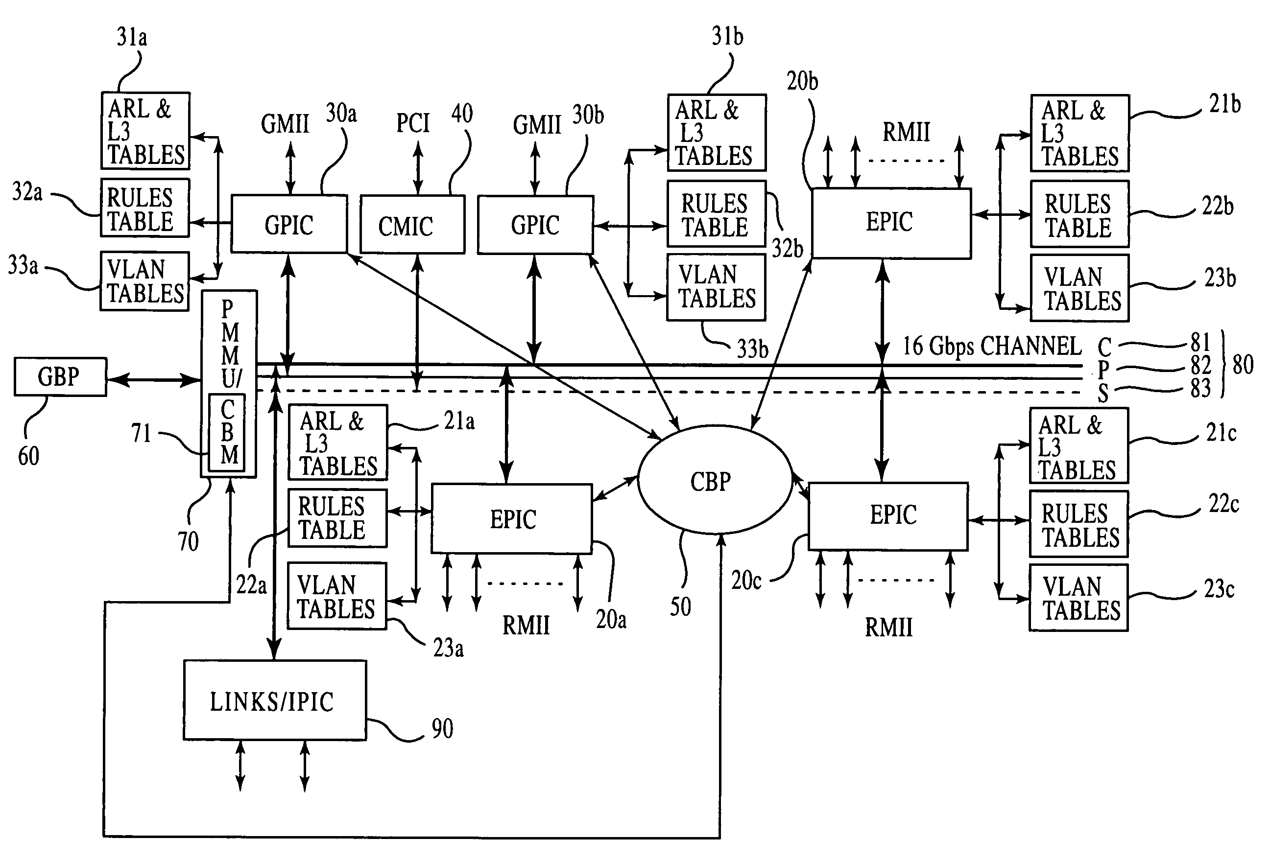
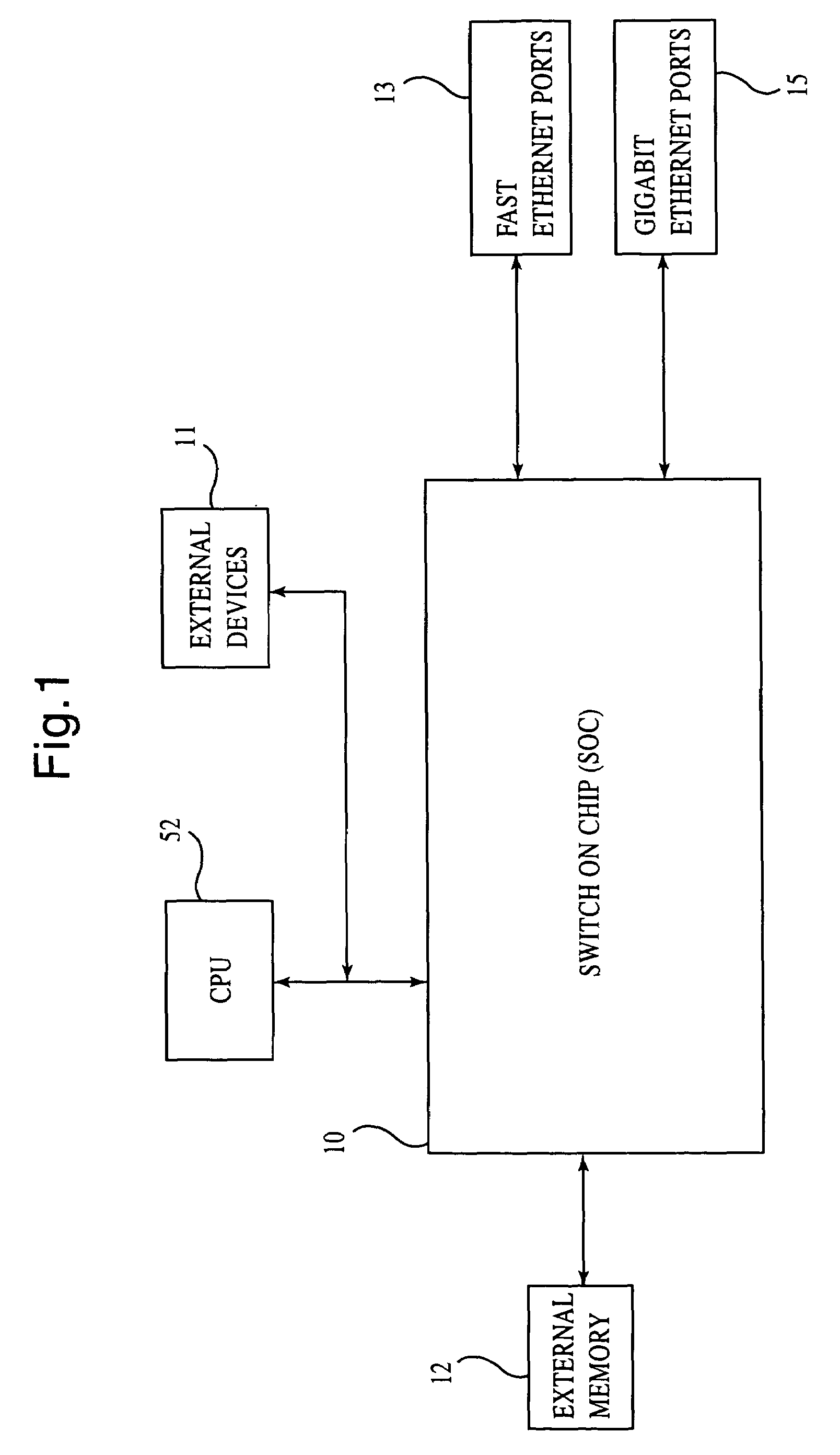
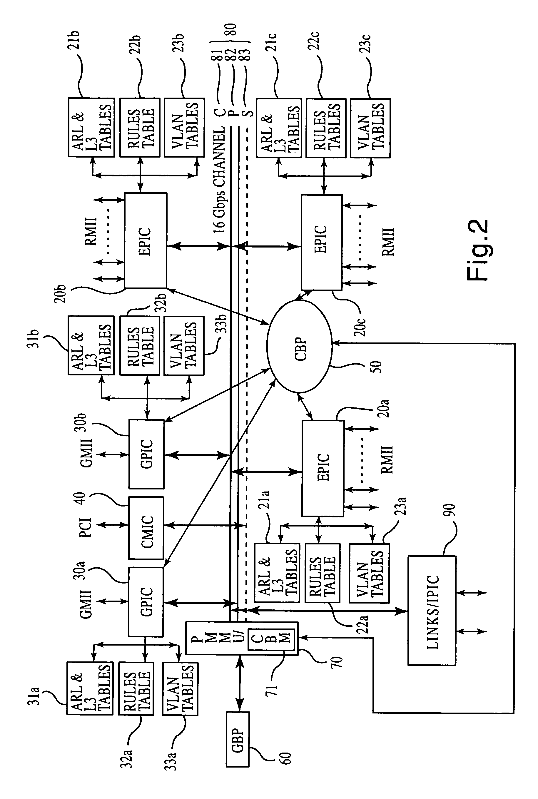
[0041]Although VOIP transmissions generally originate and are most effective in a local area network environment, often VOIP transmissions are transmitted across a wide area network to a final destination. As such, when a local network transmits VOIP packets therethrough, the VOIP packets will inherently travel through at least one network switch in traversing the local network. These switches operate to route the VOIP packet towards the final destination. However, the network switches are often congested as a result of high traffic volume in a network, and therefore, the VOIP packets being transmitted through the network may be delayed as a result of the congestion. An object of the present invention is to reduce this delay. Therefore, prior to any discussion of the specific VOIP method and apparatus of the present invention, it is beneficial to discuss an example of a general structure and configuration of a network switch capable of supporting the present invention, however, it s...


PUM


Abstract

An apparatus and method for switching VOIP packets in a data network, wherein the method includes the steps of receiving a first packet in a network switch and determining if the first packet is a VOIP packet. Further, method includes determining a dynamically negotiated VOIP port for a VOIP session from at least one of the first packet and a second packet received in the network switch, if the first packet is determined to be the VOIP packet. Finally, the method includes the steps of classifying all subsequent VOIP packets corresponding to the dynamically negotiated VOIP port in accordance with predetermined parameters. The apparatus includes a network switch having at least one data port interface controller supporting a plurality of data ports for transmitting and receiving data, and a fast filtering processor in communication with the at least one data port interface. At least one filtering table in communication with the fast filtering processor is provided, wherein the fast filtering processor is configured to snoop packets being transmitted through the network switch to trap a VOIP call setup message, and thereafter, determine a dynamically negotiated VOIP port so that all subsequent VOIP packets can be filtered and assigned an appropriate priority.

Description

REFERENCE TO RELATED APPLICATIONS[0001]This application claims priority of U.S. Provisional Patent Application Ser. No. 60 / 152,289, filed on Sep. 3, 1999. Additionally, this application is a Continuation-In-Part application of co-pending U.S. patent application Ser. No. 09 / 528,434, which was filed on Mar. 17, 2000. The contents of these earlier filed applications are hereby incorporated by reference.BACKGROUND OF THE INVENTION[0002]1. Field of the Invention[0003]The invention relates to a method and apparatus for high performance switching in local area communications networks such as token ring, ATM, Ethernet, fast Ethernet, and gigabit Ethernet environments, generally known as LANs. In particular, the present invention relates to an apparatus and method for high performance switching in local area communications networks in order to enable effective Voice Over Internet Protocol (VOIP) in a data network. Further, the resent invention relates to a new switching method and architectu...

Claims


Application Information

Patent Timeline
Patent Type & Authority Patents(United States)
IPC IPC(8): H04L12/28H04L12/56H04L12/64H04L29/06
CPCH04L12/5601H04L65/103H04L12/6418H04L29/06027H04L47/10H04L47/13H04L47/2408H04L47/2433H04L47/2441H04L47/2458H04L47/32H04L49/109H04L49/206H04L49/3072H04L49/351H04L65/80H04L65/605H04L65/104H04L12/6402H04L49/352H04L2012/6408H04L2012/6464H04L2012/6472H04L2012/6481H04L65/765H04L65/1101
Inventor LOR, KAR-WING EDWARDKALKUNTE, MOHANAMBE, SHEKHAR
Owner AVAGO TECH INT SALES PTE LTD
Why Eureka
Try Eureka