
Pneumatic tire

a pneumatic tire and tire blade technology, applied in the field of tires, can solve the problems of reducing the design parameters of the tread, high cost of the blades of the mold, etc., and achieve the effect of improving the performance and/or the durability of the tir

Active Publication Date: 2012-06-28
THE GOODYEAR TIRE & RUBBER CO
View PDF9 Cites 9 Cited by
  • Summary
  • Abstract
  • Description
  • Claims
  • Application Information

AI Technical Summary

Benefits of technology

[0007]In view of the above mentioned prior art, it is an object of the invention to improve the performance and / or the durability of a tire comprising sipes or grooves in tread blocks or tread ribs.
[0008]It is another object of the present invention to improve or at least to maintain driving mileage and fuel economy of a tire comprising sipes in the tread portion and to reduce simultaneously fatigue cracks at the bottom of the sipes.

Problems solved by technology

No complicated bottom shape of the sipes, resulting in high costs for the blades of the mold or resulting in a reduction of design parameters of the tread, is required.

Method used


Image

  • Pneumatic tire
  • Pneumatic tire
  • Pneumatic tire

Examples


Embodiment Construction

[0028]The following language is of the best presently contemplated mode or modes of carrying out the invention. This description is made for the purpose of illustrating the general principles of the invention and should not be understood in a limiting sense. The scope of the invention is best determined by reference to the appended claims. The reference numerals as depicted in the drawings are the same as those referred to in the specification.

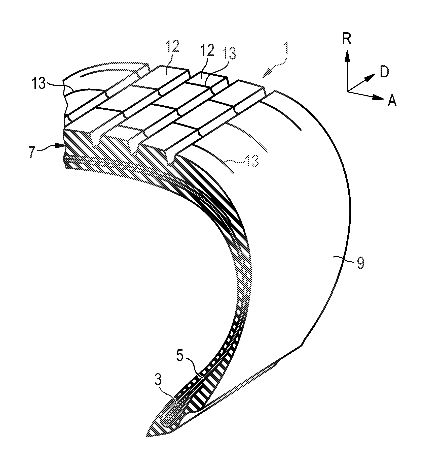
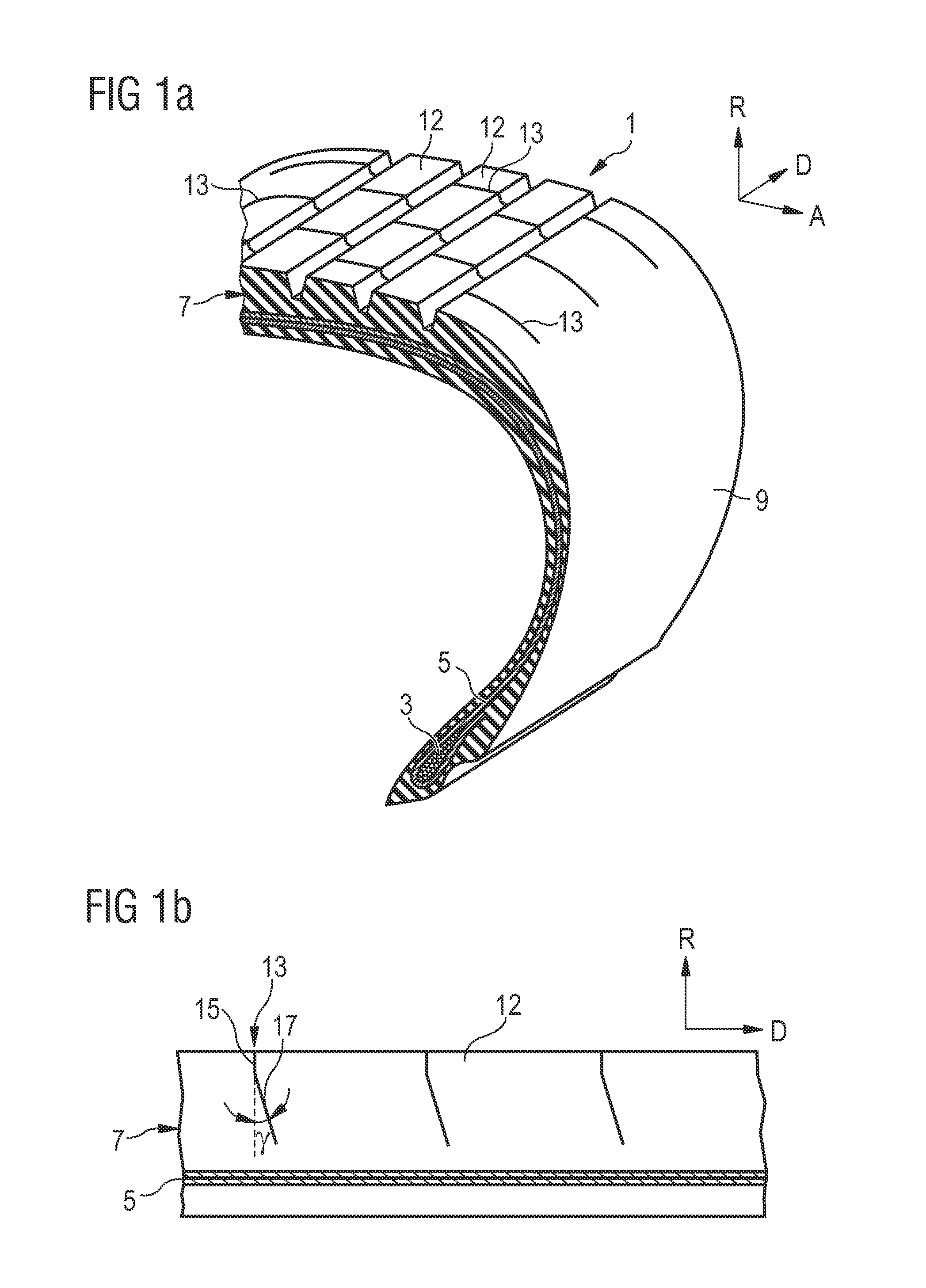
[0029]FIG. 1a depicts one preferred embodiment of the invention showing a tire 1 comprising beads 3 and a carcass ply 5 wrapped around said beads 3 and a tread 7 radially above a crown area of the tire 1. Sidewalls 9 are arranged between the tread 7 and the beads 3 of the tire 1. For the sake of a better comprehensibility, a coordinate system has been included in FIG. 1a showing the radial direction R, the axial direction A and the direction of the tire's rotation D.

[0030]In the embodiment depicted in FIG. 1a the tread comprises tread ribs 12....


PUM


Abstract

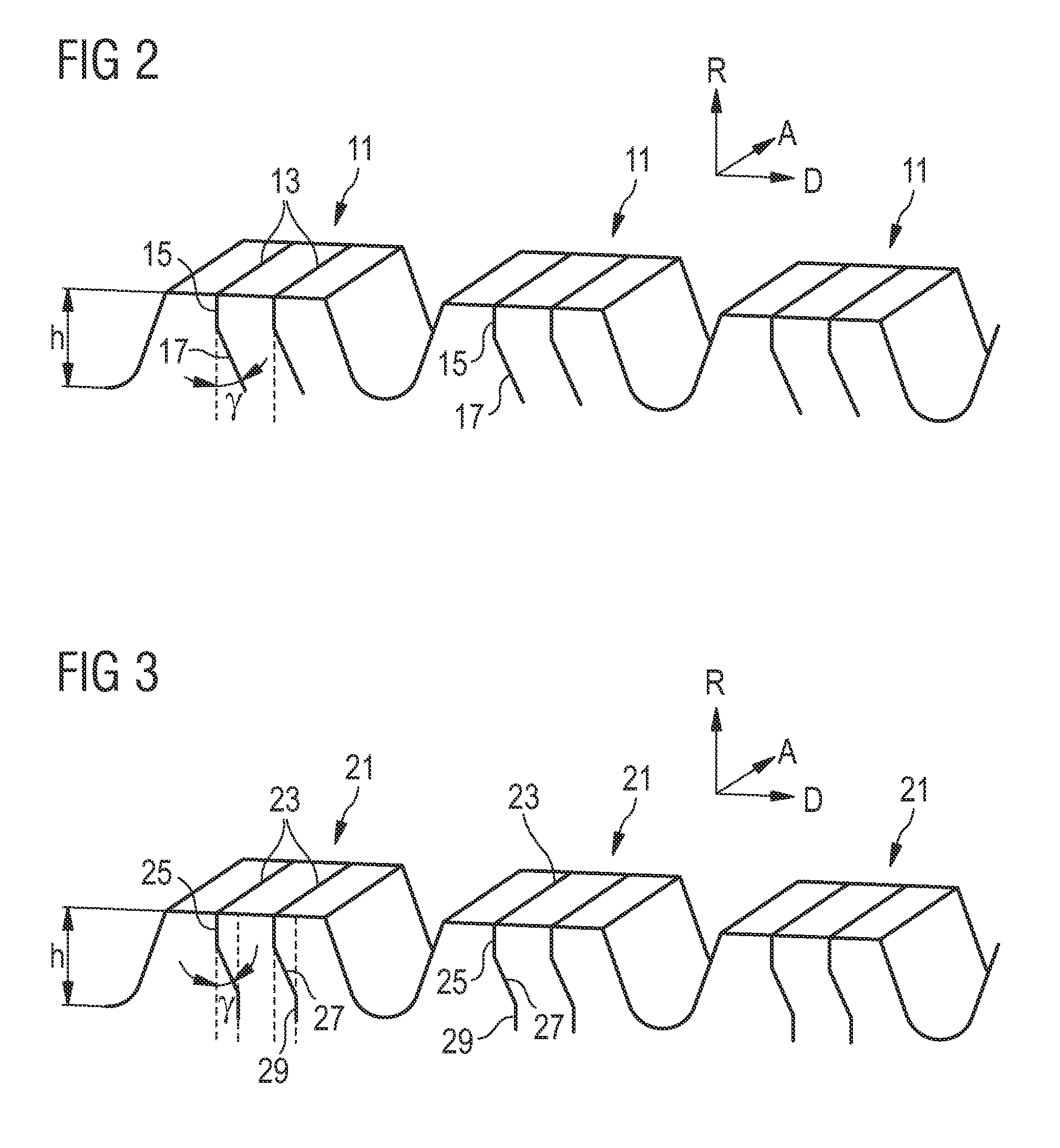
The present invention is directed to a pneumatic tire 1, comprising at least one pair of parallel annular beads 3; at least one carcass ply wrapped 5 around said beads 3; a tread 7; and first and second sidewalls 9 disposed between said tread 7 and one of said at least one pair of beads 3. In accordance with an embodiment of the invention, the tread comprises tread blocks 11 and / or tread ribs 12, wherein the tread blocks 11 and / or tread ribs 12 comprise sipes 13 extending essentially in an axial direction A of the tire 1, the sipes 13 consisting of an upper portion 15 essentially aligned with the radial direction R of the tire and a lower portion 17 inclined in the direction of rotation D of the tire 1.

Description

FIELD OF THE INVENTION[0001]The present patent application is directed to a tire, in particular a pneumatic tire comprising narrow grooves in blocks or ribs of the tire's tread.BACKGROUND OF THE INVENTION[0002]Multiple types of tires comprise treads having narrow grooves in their tread blocks or tread ribs. In particular, in modern long haul drive tires such narrow grooves or sipes are part of the tread design. In general, such sipes may increase mileage and fuel economy so that they have often been applied in the past.[0003]However, it has been observed that under heavy duty or extensive use such sipes may provoke fatigue cracks starting to propagate at the bottom of the sipes.[0004]To overcome this problem, typical solutions of the prior art utilize an increased groove bottom radius of the sipes, e.g. by using ball-bottom blades in the mold. However, this is only a partial solution which leads to losses of design parameters and may result in drawbacks in relation to driving mileag...

Claims


Application Information

Patent Timeline
Patent Type & Authority Applications(United States)
IPC IPC(8): B60C11/12
CPCB60C2011/129B60C11/0306B60C11/124B60C2011/1209B60C11/1218B60C11/1204B60C11/1259B60C11/1272
Inventor DE BARSY, OLIVIERSCHEUREN, DANIEL
Owner THE GOODYEAR TIRE & RUBBER CO
Learn More