
Touch-sensitive system and method for controlling the operation thereof

a technology of touch-sensitive systems and operation control, applied in the direction of instruments, computing, electric digital data processing, etc., can solve the problems of unintentional interruption of optical transmission paths, inability to cover the whole surface of optical transmission, information retrieved from the system being erroneous or incomplete, etc., and achieve the effect of fast response for new touches

Inactive Publication Date: 2012-06-28
FLATFROG LAB
View PDF13 Cites 64 Cited by
  • Summary
  • Abstract
  • Description
  • Claims
  • Application Information

AI Technical Summary

Benefits of technology

[0013]According to this aspect, the mode selector may thus be adapted for saving energy in touch-sensitive systems with in- and out-coupling points along the sides of the panel. One advantage of this aspect is the ability to change the emission pattern to reduce the energy consumption of the touch-sensitive system, and / or to enable a higher updating frequency (frame rate) of the touch-sensitive system for a given energy consumption. The change in emission pattern may also be used to achieve different resolutions on different parts of the touch surface, e.g. the resolution can be selectively increased on part of the touch surface that has many touches.
[0014]Embodiments of the invention are designed to allow for reduced energy consumption during both inactive (no touches on the touch surface) and active use of the touch-sensitive system.

Problems solved by technology

If the display screen is contaminated by e.g. fingerprints, the optical transmission path may become unintentionally interrupted and the information retrieved from the system erroneous or incomplete as the contaminated surface becomes insensitive to touches.
There is also no guarantee that the whole surface can be covered by optical transmission, as the above surface enablement may require a bezel around the panel.
If contaminants are collected in front of one of the emitters or detectors there will always be blocked light paths.
Systems that has a bezel around the panel surface are very prone to collecting dust, grease, etc at the bezel position.
Placing emitters and detectors at the bezel position is therefore not desired, and it may thus be hard to illuminate the whole surface.
The algorithms used are not specially adapted to detect changes in an FTIR system.
Nevertheless, an FTIR system has the potential of being less sensitive to contaminants such as fingerprints and grease on the panel, as the contaminants only absorb a fraction of the light along a path through the panel.

Method used


Image

  • Touch-sensitive system and method for controlling the operation thereof
  • Touch-sensitive system and method for controlling the operation thereof
  • Touch-sensitive system and method for controlling the operation thereof

Examples


Embodiment Construction

[0033]Throughout the description, the same reference numerals are used to identify corresponding elements / steps.

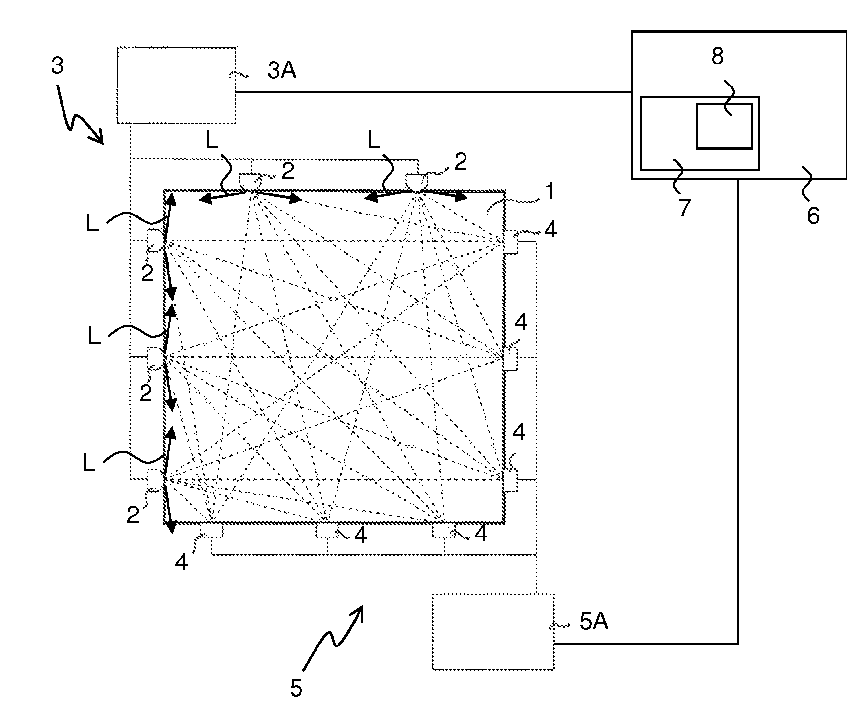
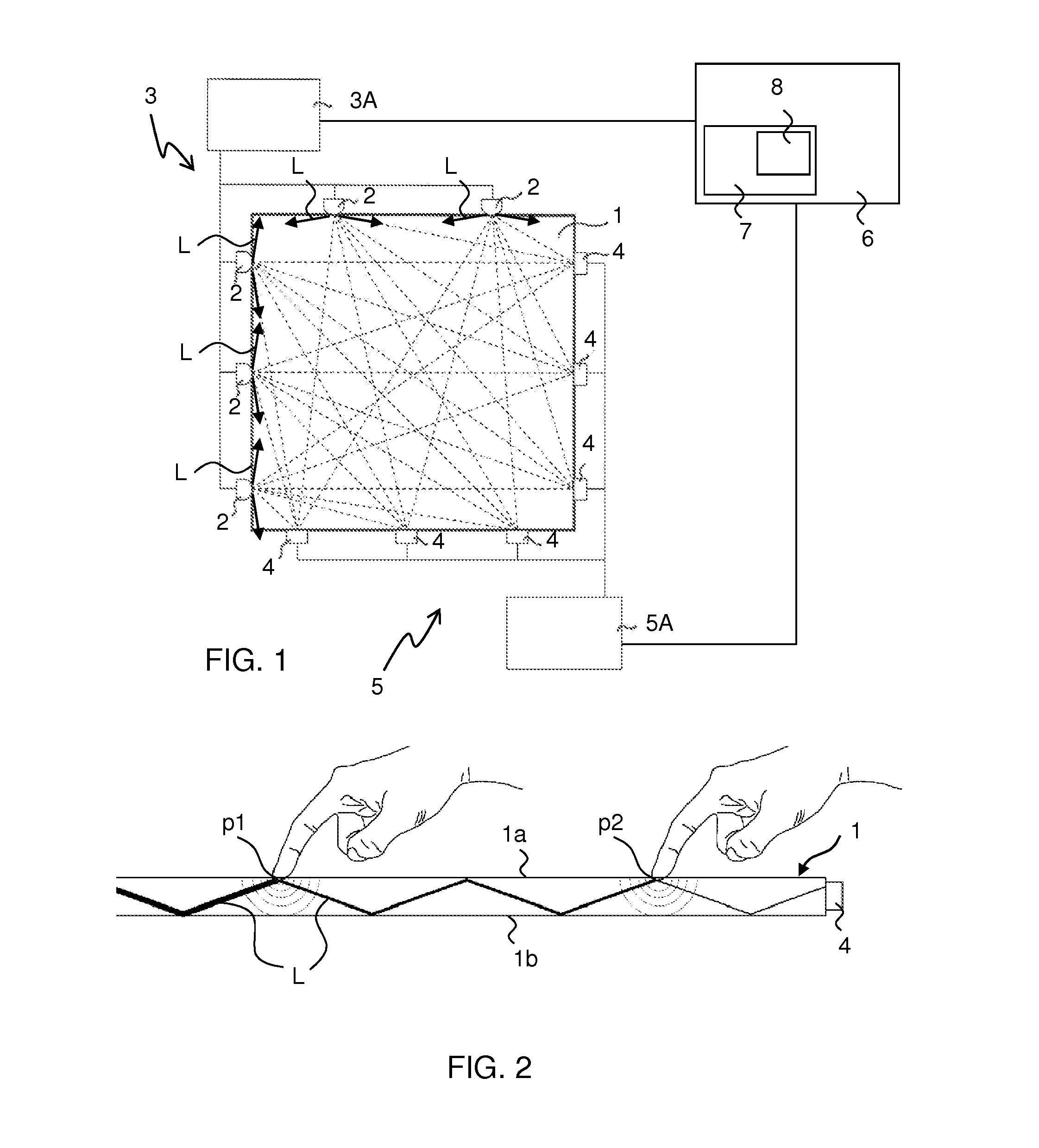
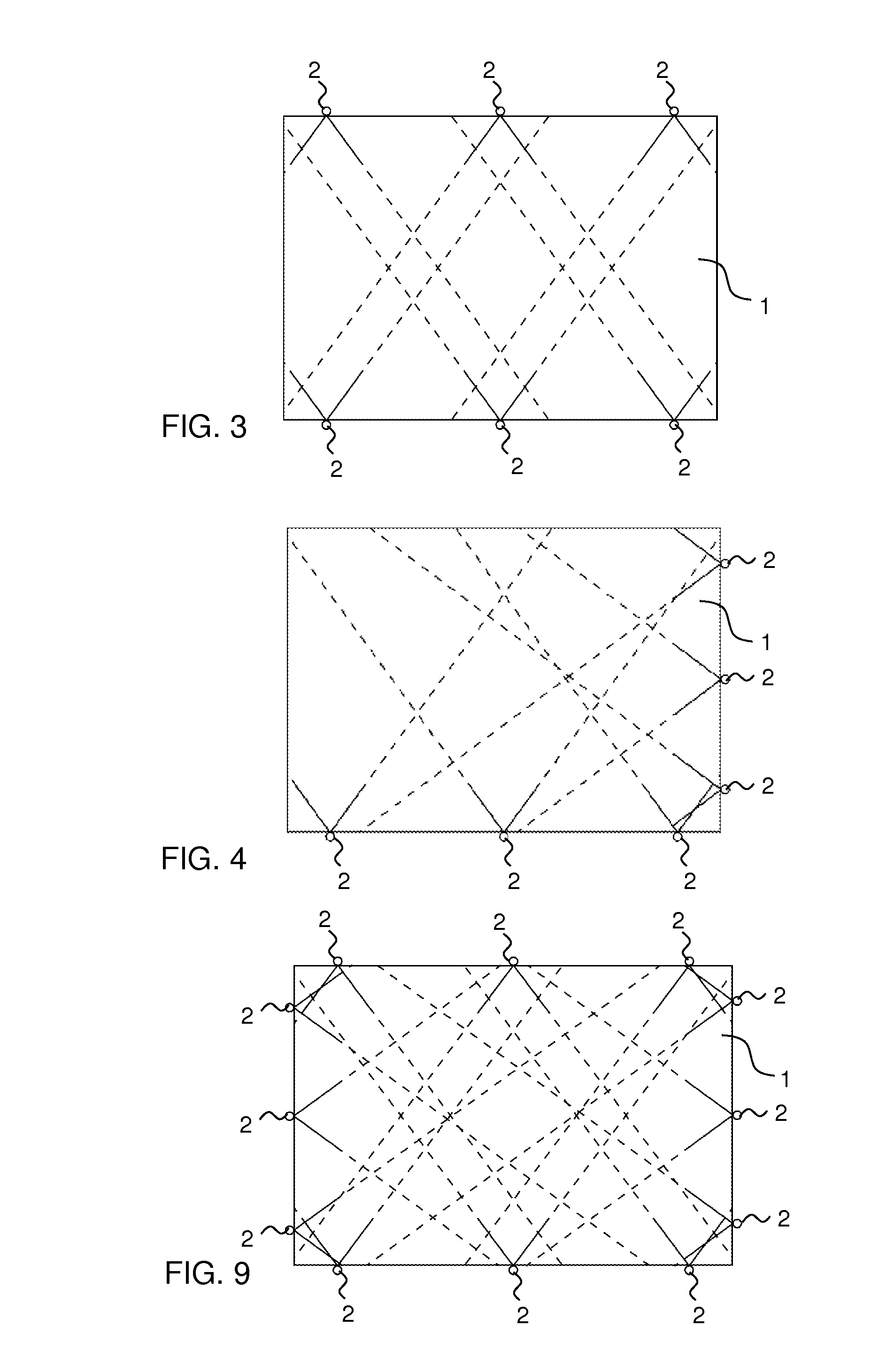
[0034]An example of a touch-sensitive system is shown in FIG. 1, comprising a panel 1, an illumination arrangement 3 comprising emitters 2 and an illumination control unit 3A, and a light detection arrangement 5 comprising detectors 4 and a detection control unit 5A. The touch-sensitive system is according to one embodiment a multi-touch system, thus enabling detection of a multiplicity of touches. The emitters 2 introduce light L into the panel at in-coupling points, an in-coupling point defining a point on the panel 1 where light L from an emitter 2 enters the panel 1. The detectors 4 detects the energy of the light at out-coupling points, an out-coupling point defining a point on the panel where the light propagating in the panel 1 leaves the panel 1 for subsequent detection by a detector 4. It is only the in-coupling and out-coupling points of the detectors 4 and emitt...


PUM


Abstract

A touch-sensitive system comprises a light transmissive panel defining a touch surface and an opposite surface; an illumination arrangement comprising emitters configured to introduce light into the panel for propagation in the panel in an emission pattern; a light detection arrangement comprising detectors configured to receive the light propagating in the panel. A control unit is arranged to control the operation of the touch-sensitive system. The control unit executes a control method to monitor the light received in the light detecting arrangement for detection of touches on the touch surface, the touches attenuating the light propagating in the panel. The control method also selects a mode for the emission pattern in dependence of the occurrence of touches on the touch surface and controls the emission pattern in accordance with the selected mode.

Description

CROSS-REFERENCE TO RELATED APPLICATIONS[0001]The present application claims the benefit of Swedish patent application No. 0901145-3, filed on Sep. 2, 2009, and U.S. provisional application No. 61 / 272,215, filed on Sep. 2, 2009, both of which are incorporated herein by reference.FIELD OF THE INVENTION[0002]The present invention relates to touch-sensitive systems, and methods for operation control in relation to such systems.BACKGROUND OF THE INVENTION[0003]Touch-sensitive panels are increasingly being used for providing input to computers, electronic measurements and test equipment, gaming devices etc. The panel may be provided with a graphical user interface (GUI) for a user to interact with using e.g. a pointer, stylus or one or more fingers.[0004]To be able to provide touch sensitivity to the panel, cameras may be used to capture light scattered off the point(s) of touch on the panel, or by incorporation of resistive wire grids, capacitive sensors, strain gauges etc. into the pane...

Claims


Application Information

Patent Timeline
IPC IPC(8): G06F3/042
CPCG06F3/0421G06F1/3262G06F2203/04109G06F3/0304G06F3/0416
Inventor CHRISTIANSSON, TOMASWASSVIK, OLA
Owner FLATFROG LAB
Features
  • Generate Ideas
  • Intellectual Property
  • Life Sciences
  • Materials
  • Tech Scout
  • Unparalleled Data Quality
  • Higher Quality Content
  • 60% Fewer Hallucinations
Learn More