3D image sensor

a technology of image sensor and image, applied in the direction of distance measurement, instruments, television systems, etc., can solve the problems of difficult manufacture of mobile devices using this method, difficult to adapt the method to the measurement of short distances, and relatively complex use of this technique to perform an automated mapping of distance to objects contained in a scene. , to achieve the effect of low response tim

Active Publication Date: 2012-06-28
STMICROELECTRONICS (GRENOBLE 2) SAS
View PDF13 Cites 28 Cited by
  • Summary
  • Abstract
  • Description
  • Claims
  • Application Information

AI Technical Summary

Benefits of technology

[0011]An embodiment aims at providing an image sensor enabling to determine the distance to objects contained in a scene, having a low response time and overcoming all or part of the disadvantages of prior art sensors.

Problems solved by technology

Using this technique to perform an automated mapping of the distance to objects contained in a scene (stereoscopic method) is relatively complex.
It is thus difficult to manufacture mobile devices using this method.
This method is however not adapted to the measurement of short distances.
Indeed, in this case, the time taken by the wave to travel to the object and back is too short to be easily detected by a sensor and does not enable to accurately determine close distances.
Further, this method is not compatible with the performing of an instantaneous mapping of distances to objects.
Indeed, such an instantaneous determination would need the transmitted wave to have a very high power to reach an extensive area of the image, which is incompatible with the forming of portable devices.
However, such methods are only accurate if the scene is not moving: they may need too long a response time to acquire information corresponding to a moving scene.

Method used


Image

  • 3D image sensor
  • 3D image sensor
  • 3D image sensor

Examples


Embodiment Construction

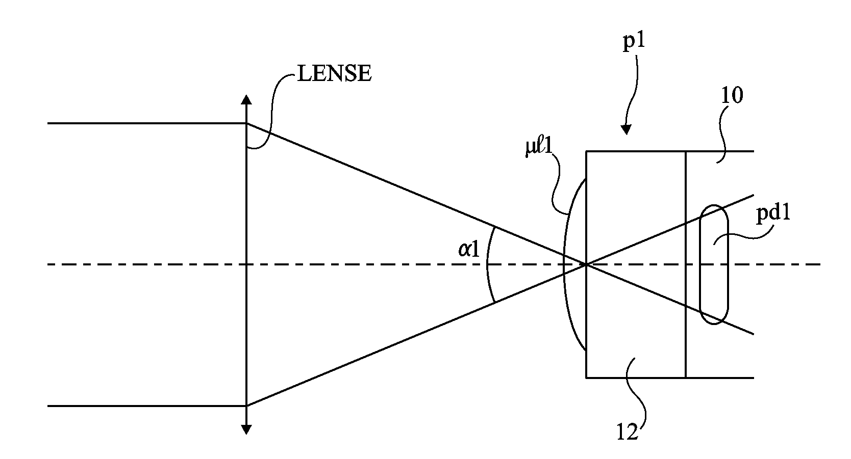
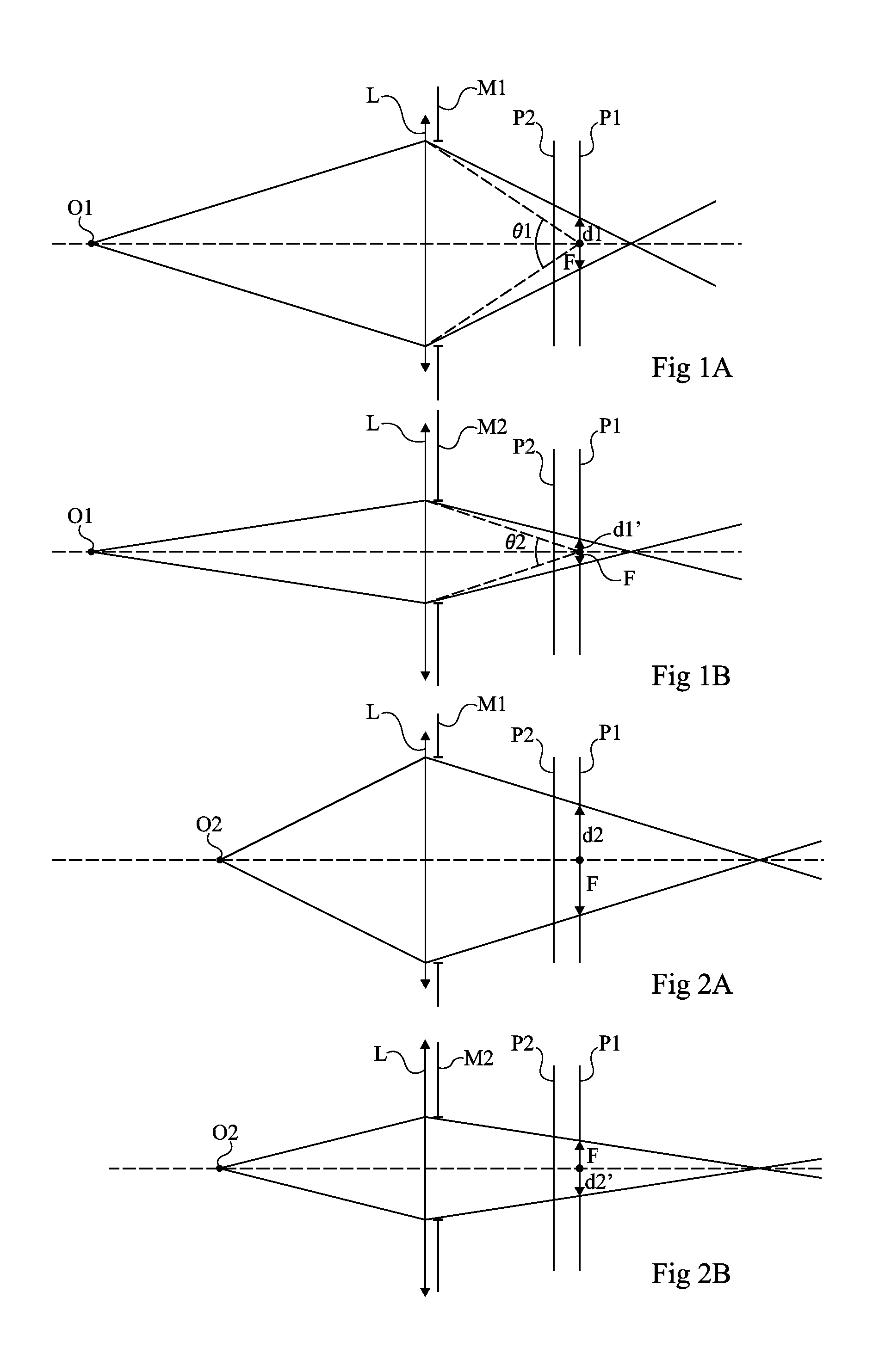
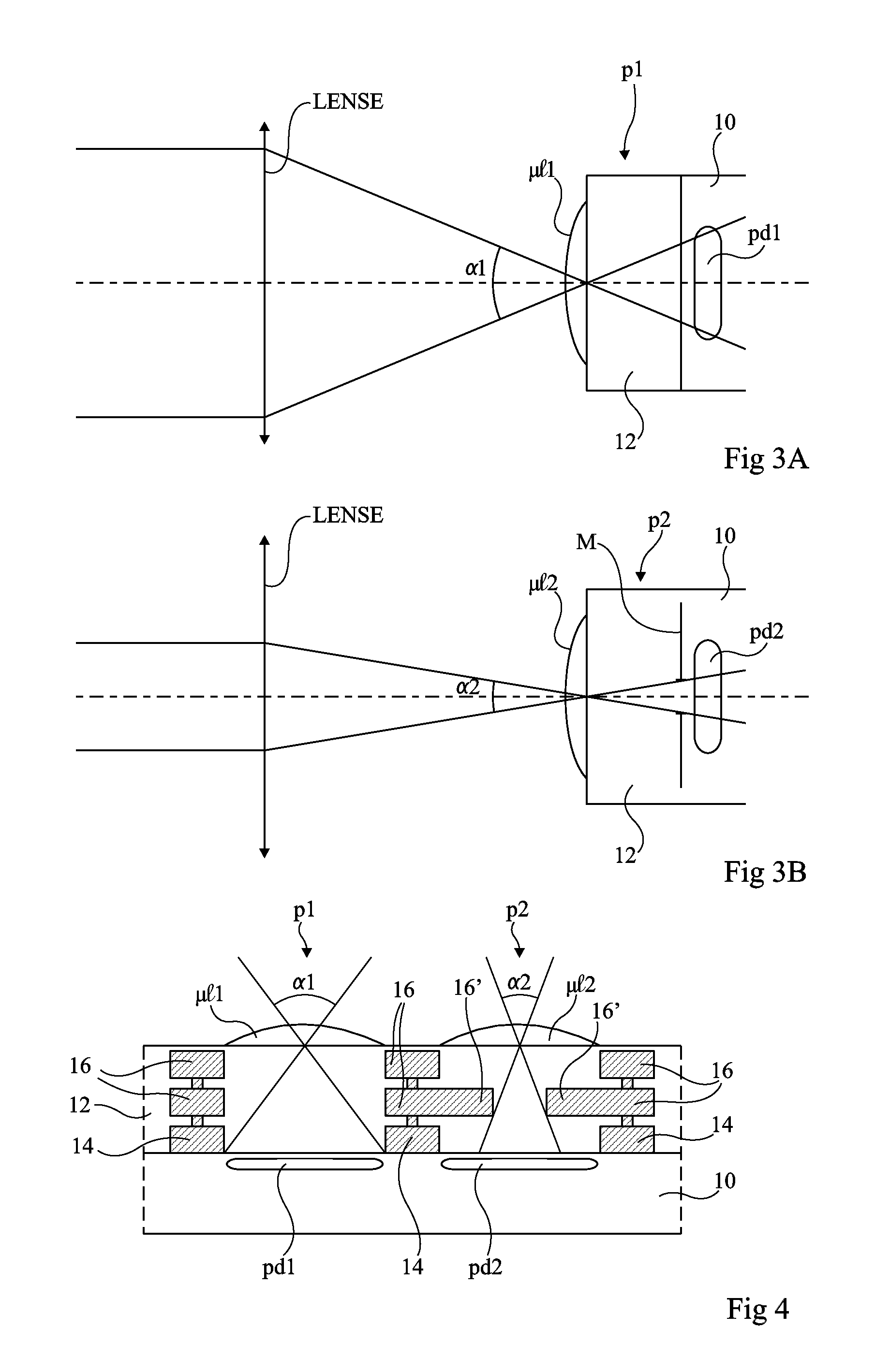
[0029]FIGS. 1A, 1B, 2A, and 2B illustrate the basic operating principle of an image sensor according to an embodiment.

[0030]These drawings show an optical device comprising a converging lens L. The focal point of the lens on its optical axis is called F and its focal plane is called P1. A shutter, placed against the lens, is provided to limit its angular aperture. In the case of FIGS. 1A and 2A, a shutter M1 only slightly limiting the angular aperture of the lens is provided while, in the case of FIGS. 1B and 2B, a second shutter M2, having a smaller opening than shutter M1, is provided.

[0031]The angular aperture of lens L is defined by angle θ1 in FIG. 1A, respectively angle θ2 in FIG. 1B, formed between two beams arriving onto the shutter contour from an infinite distance, at the level of focal point F.

[0032]In FIGS. 1A and 1B, an object O1 is placed on the optical axis of the lens at a first distance from it. In focal plane P1 of the lens, object O1 forms a blurred image having a...


PUM


Abstract

An integrated image sensor capable of determining the distance to objects contained in a scene including at least a set of first pixels and a set of second pixels, the first and second pixels being alternately distributed in an array, the first pixels having a different angular aperture than the second pixels.

Description

CROSS REFERENCE TO RELATED APPLICATIONS[0001]This application claims the priority benefit of French patent application Ser. No. 10 / 61073 filed on Dec. 22, 2010, entitled THREE-DIMENSIONAL IMAGE SENSOR, which is hereby incorporated by reference to the maximum extent allowable by law.BACKGROUND[0002]1. Technical Field[0003]Embodiments relate to a three-dimensional integrated image sensor enabling to obtain information relative to the distance to objects contained in a scene. More specifically, the present invention relates to such a sensor capable of detecting objects at macroscopic distances.[0004]2. Discussion of the Related Art[0005]“Three-dimensional (3D) macroscopic image sensor” here designates image sensors that allow measurement of the remoteness of objects located at distances greater than approximately one centimeter.[0006]Many techniques for acquiring three-dimensional images and obtaining information as to the distance to objects are known. Among these, stereo vision techn...

Claims


Application Information

Patent Timeline
Patent Type & Authority Applications(United States)
IPC IPC(8): H04N13/02
CPCG01C3/085H01L27/14603H01L27/14645H01L27/14625H01L27/14623H01L27/14605
Inventor VAILLANT, JEROME
Owner STMICROELECTRONICS (GRENOBLE 2) SAS
Why Eureka
Try Eureka