Image sensor unit and image reader

a sensor unit and image technology, applied in the field of contact image sensor unit and image reader, can solve the problems of image sensor, increased size, increased cost, etc., and achieve the effect of preventing light leakage and preventing cracking

Inactive Publication Date: 2012-06-28
CANON COMPONENTS INC
View PDF9 Cites 30 Cited by
  • Summary
  • Abstract
  • Description
  • Claims
  • Application Information

AI Technical Summary

Benefits of technology

[0010]The present invention has been developed in view of the above-described circumstances. An object of the present invention is to provide an image sensor unit that enables possible leakage light to be prevented without the need to increase the size of the image sensor unit and which also enables a light guide to be prevented from suffering a crack, wear, and the like.

Problems solved by technology

However, disadvantageously, the image sensor described in Japanese Laid-Open Patent Publication No. 2004-146870 has an increased size owing to a light guide cover provided therein to cover the light guide.
For an image sensor without a light guide cover, additional components are required, disadvantageously leading to increased costs.
Furthermore, the image sensor may suffer a crack or the like when the light guide expands or contracts as a result of, for example, a variation in atmospheric temperature and / or atmospheric humidity.

Method used


Image

  • Image sensor unit and image reader
  • Image sensor unit and image reader
  • Image sensor unit and image reader

Examples


first embodiment

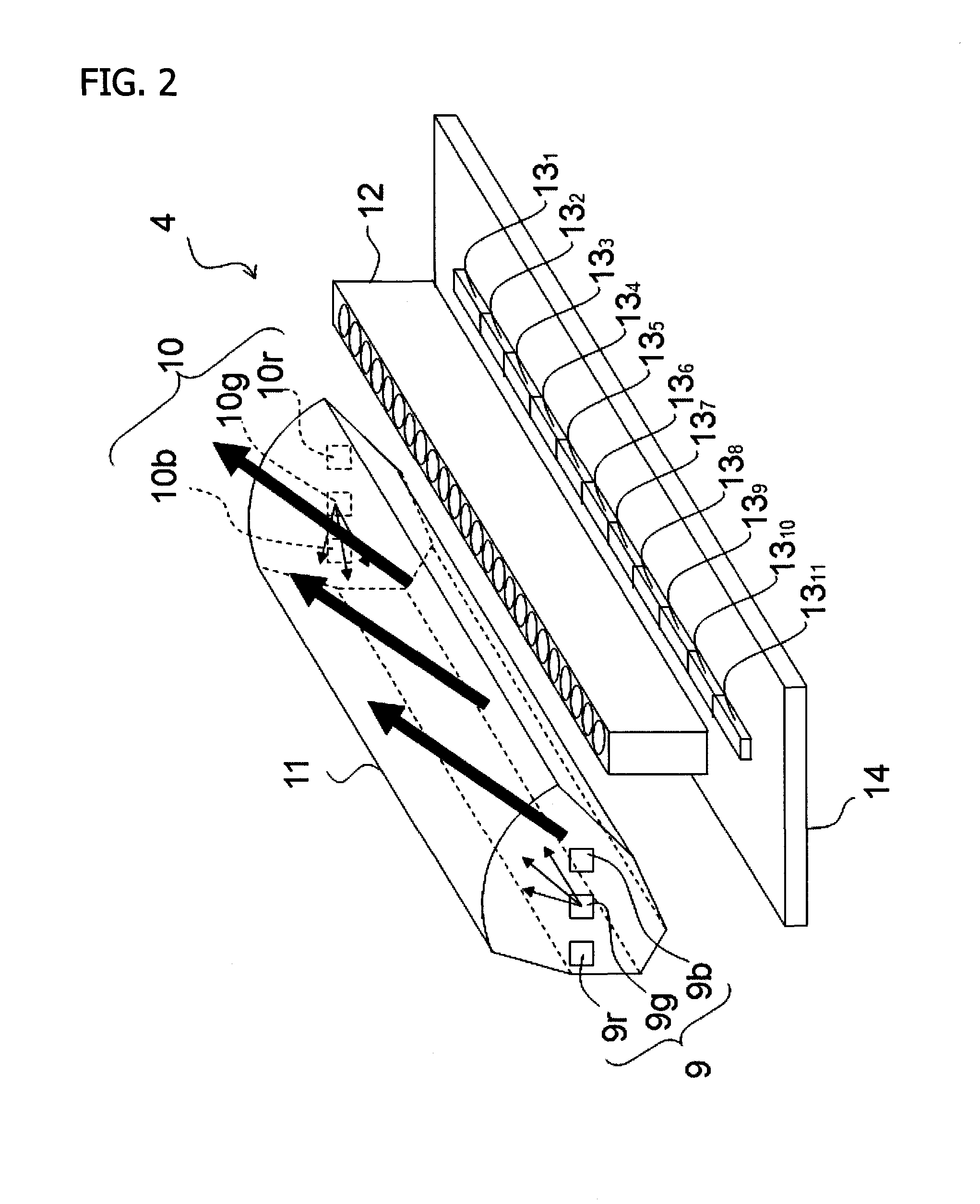
[0053]FIG. 4 is a perspective view showing a configuration of the image sensor unit 4 according to a first embodiment to which the present invention is applicable. FIG. 5 is a perspective view showing the detailed shape of a light blocking member 16. A frame is shown by reference numeral 15 and serves as a support that supports components of the image sensor unit 4. The following components are attached to and supported by the frame 15: a first light source 9 and a second light source 10, a light guide 11, a rod lens array 12, and a sensor substrate 14 with photoelectric conversion elements 13k mounted thereon.

[0054]The light blocking member is shown by reference numeral 16. The light blocking member 16 includes an opening shape substantially similar to a cross-sectional shape of the light guide 11 in the longitudinal direction thereof. The light blocking member 16 is shaped like a cylinder into which the light guide 11 can be inserted.

[0055]The light blocking member 16 is positione...

second embodiment

[0084]FIG. 8 is a perspective view showing a configuration of an image sensor unit 4 according to a second embodiment to which the present invention is applicable. FIG. 9 is a perspective view showing the detailed shape of a light blocking member 16 according to the second embodiment.

[0085]Members of the second embodiment which provide the same functions as those in the above-described first embodiment are denoted by the same reference numerals and will not be described below.

[0086]The light blocking member 16 includes a first light blocking member 16a and a second light blocking member 16b positioned so as to cover the respective longitudinally opposite ends of the image sensor unit 4. Each of the light blocking members 16a and 16b has an opening shape substantially similar to the cross-sectional shape of the light guide 11 perpendicular to the longitudinal direction thereof. Each of the light blocking members 16a and 16b is formed like a cylinder into which the light guide 11 can ...


PUM


Abstract

A protruding locking pawl is provided at an end of a light guide which corresponds to a first light input surface. A recessed locking portion is formed in a frame so that the locking pawl can be locked in the locking portion. A light blocking member is slidably loosely inserted into a position where the light blocking member covers a longitudinal end of the light guide which corresponds to a second light input surface. Even if expansion and contraction occurs in the longitudinal direction of the light guide, the design dimensions of a first gap A and a second gap B can be maintained; the first gap A is formed between the first light input surface and a first light source, and the second gap B formed between the second light input surface and a second light source. Therefore, possible leakage current can be prevented.

Description

CROSS-REFERENCE TO RELATED APPLICATIONS[0001]This application is based upon and claims the benefit of priority of the prior Japanese Patent Application No. 2010-293227, filed on Dec. 28, 2010, the entire contents of which are incorporated herein by reference.BACKGROUND OF THE INVENTION[0002]1. Field of the Invention[0003]The present invention relates to a contact image sensor unit and an image reader using the contact image sensor unit.[0004]2. Description of the Related Art[0005]In an image sensor unit with light sources installed at the respective opposite ends of a light guide in a longitudinal direction thereof (main scanning direction), leakage light may result from, for example, a variation in atmospheric temperature and / or atmospheric humidity.[0006]Thus, an image reader (image sensor) described in Japanese Laid-Open Patent Publication No. 2004-146870 has been proposed.Patent Document 1[0007]Japanese Laid-Open Patent Publication No. 2004-146870[0008]However, disadvantageously...

Claims


Application Information

Patent Timeline
Patent Type & Authority Applications(United States)
IPC IPC(8): H04N1/04
CPCH04N1/02481H04N1/0249H04N1/02835H04N2201/02435H04N2201/02456H04N2201/02458H04N2201/02462H04N2201/02474H04N2201/02481H04N2201/02449
Inventor SHIMODA, SHUUICHIYOSHIDA, HIDEMASAKIYOTA, HIDEOMURAKAMI, HIROYUKI
Owner CANON COMPONENTS INC
Why Eureka
Try Eureka