
Fixed focus lens

a fixed focus and lens technology, applied in the field of fixed focus lenses, can solve the problems of limiting the degree of freedom in design, not facilitating simplification, and not sufficiently achieving the effect of reducing siz

Active Publication Date: 2012-06-28
TAMRON
View PDF1 Cites 16 Cited by
  • Summary
  • Abstract
  • Description
  • Claims
  • Application Information

AI Technical Summary

Benefits of technology

0.3<F1 / F<1.1  (6)

Problems solved by technology

Consequently, fixed focus lenses used in single lens reflex cameras must have a long back focus, limiting degrees of freedom in terms of design.
The optical system disclosed in Japanese Patent No. 3950571 achieves simplification in that the focusing lens group is configured by one negative lens, nonetheless, configurations of other lens groups include numerous lenses and do not facilitate simplification.
For these reasons the optical system disclosed in Japanese Patent No. 3950571 does not sufficiently achieve reductions in size and is not suitable for recent mirror-less cameras of which further size reductions are demanded.
The optical system disclosed in Japanese Patent No. 3445554 achieves a simpler configuration than the optical system disclosed in Japanese Patent No. 3950571, but with respect to the focusing stroke, the focusing sensitivity of the image focusing is small and consequently, when images are captured at the minimum object distance, the focusing group has to be moved greatly and thus, a reduction in the size of the optical system cannot be achieved.
The optical system disclosed in Japanese Patent Application Laid-Open Publication No. 2003-43348 facilitates simplification by a two-lens configuration of the focusing group, but here again, since the focusing sensitivity is small, when images are captured at the minimum object distance, the focusing group has to be moved greatly and thus, a reduction in the size of the optical system cannot be achieved.
Thus, conventional fixed focus lenses, such as those recited in the patent documents above do not achieve sufficient size and weight reductions.

Method used


Image

  • Fixed focus lens
  • Fixed focus lens
  • Fixed focus lens

Examples


Embodiment Construction

[0028]Referring to the accompanying drawings, exemplary embodiments according to the present invention are explained in detail below.

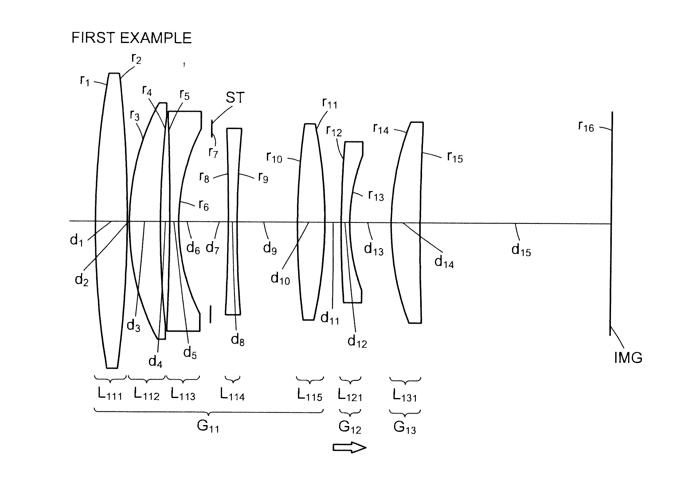
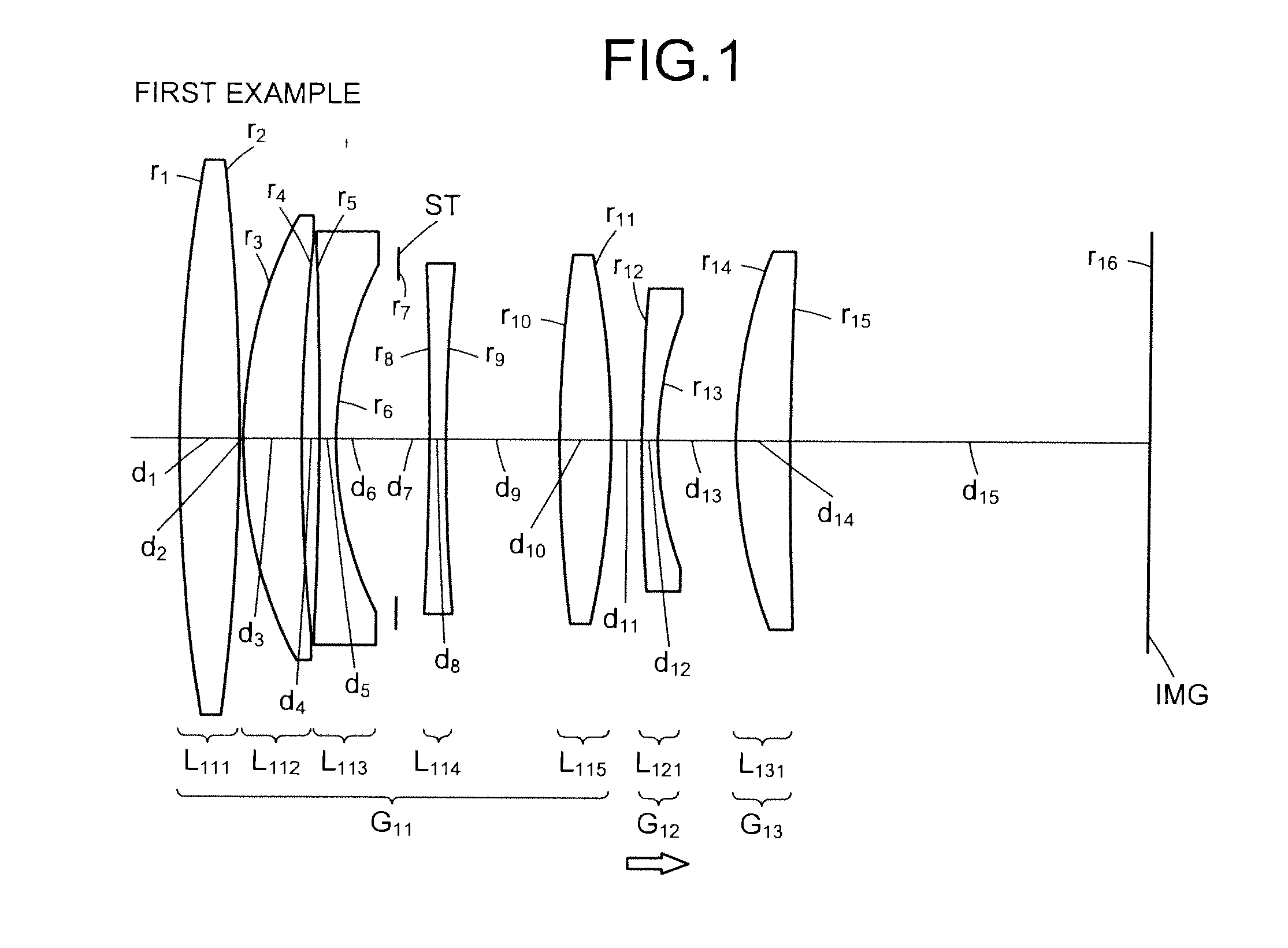
[0029]A fixed focus lens according to the present invention includes sequentially from the object side, a first lens group having a positive refractive power, a second lens group having a negative refractive power, and a third lens group having a positive refractive power.

[0030]To reduce the overall length of the optical system, the combined magnification of the second and the third lens groups, which are subsequent the first lens group, is preferably increased and the focal length of the first lens group is shortened. However, if the magnification of the second lens group and the third lens group is unnecessarily large, aberration occurring at the first lens group is intensified at subsequent groups. To prevent this negative effect, the first lens group has to minimize the aberration that occurs therein. To favorably correct aberration by the first le...


PUM


Abstract

A fixed focus lens comprising, sequentially from an object side, a first lens group having a positive refractive power; a second lens group having a negative refractive power; and a third lens group having a positive refractive power. The first lens group includes an aperture stop. The second lens group is configured by a single lens element. During focusing, the second lens group moves along an optical axis and the first lens group and the third lens group are fixed with respect to an imaging plane.

Description

BACKGROUND OF THE INVENTION[0001]1. Field of the Invention[0002]The present invention relates to a fixed focus lens used in 35 mm cameras, video cameras, digital still cameras, and the like.[0003]2. Description of the Related Art[0004]To make a captured image and the viewfinder image coincide, single lens reflex cameras are equipped with a mechanism by which light that has passed through the imaging lens is reflected by a mirror placed in front of the film and the light is guided to an optical viewfinder. Consequently, fixed focus lenses used in single lens reflex cameras must have a long back focus, limiting degrees of freedom in terms of design. Digital cameras, on the other hand, merely have to display the captured image on an electronic viewfinder to accomplish the same thing as conventional single lens reflex cameras. Therefore, by omitting the optical viewfinder and the mirror for guiding light to form the image at the optical viewfinder, a compact apparatus is realized, the s...

Claims


Application Information

Patent Timeline
Patent Type & Authority Applications(United States)
IPC IPC(8): G02B9/14
CPCG02B13/00G02B9/12G02B13/0015G02B9/64G02B9/62
Inventor ADACHI, NOBUYUKIOBIKANE, YASUHIKOSAKAI, TAKAHIKO
Owner TAMRON
Learn More