Image Forming Apparatus

a technology of forming apparatus and forming roller, which is applied in the direction of electrographic process apparatus, instruments, optics, etc., can solve the problems of toner deterioration, black, deterioration and vanishing, and strong friction, so as to reduce wear. , the effect of reducing the potential for deterioration of toner

Active Publication Date: 2012-06-28
BROTHER KOGYO KK
View PDF7 Cites 0 Cited by
  • Summary
  • Abstract
  • Description
  • Claims
  • Application Information

AI Technical Summary

Benefits of technology

[0008]Aspects of the present disclosure may provide an image forming apparatus which is configured to reduce a potential for deterioration of toner and wearing of developing rollers resulting from rubbing of photosensitive drums and the developing rollers. In one example, an image forming apparatus may be configured to reduce the potential for deterioration of toner and wearing of developing rollers without having to provide a separation mechanism that separates the photosensitive drums and the developing rollers from each other.

Problems solved by technology

In this configuration, when the developing rollers rotate in accordance with rotation of the photosensitive drums, toner particles may rub against each other, resulting in toner deterioration.
However, when all photosensitive drums are still rotating in monochrome printing, toner between the photosensitive drums and the developing rollers, except for black, deteriorates and vanishes, and a strong friction is produced therebetween.
However, in the above described image forming apparatus, the separation mechanism may involve inclusion of many components and thus may be complicated in structure and / or costly.

Method used


Image

  • Image Forming Apparatus
  • Image Forming Apparatus
  • Image Forming Apparatus

Examples


first embodiment

[0020]An illustrative first embodiment of the disclosure will be described in detail with reference to the accompanying drawings. An image forming apparatus according to illustrative aspects of the disclosure is applied to a color printer 1.

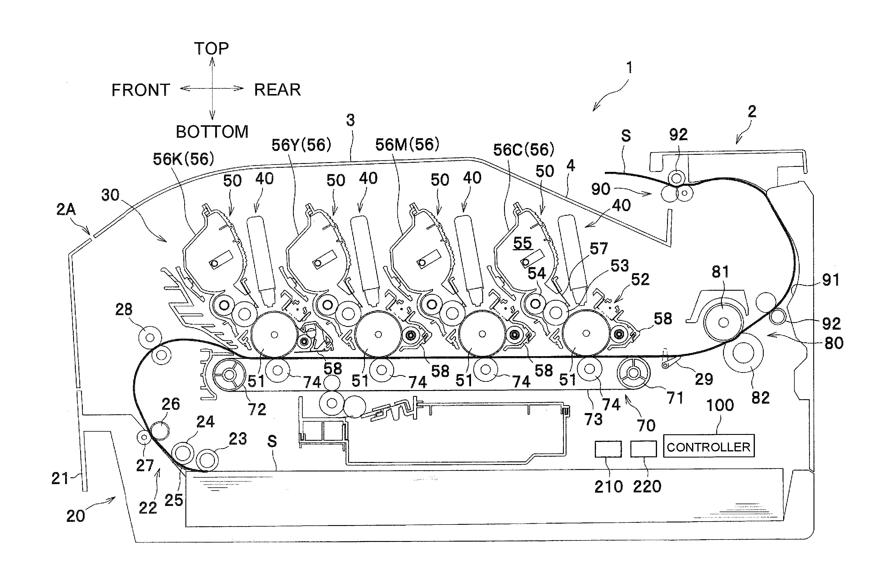
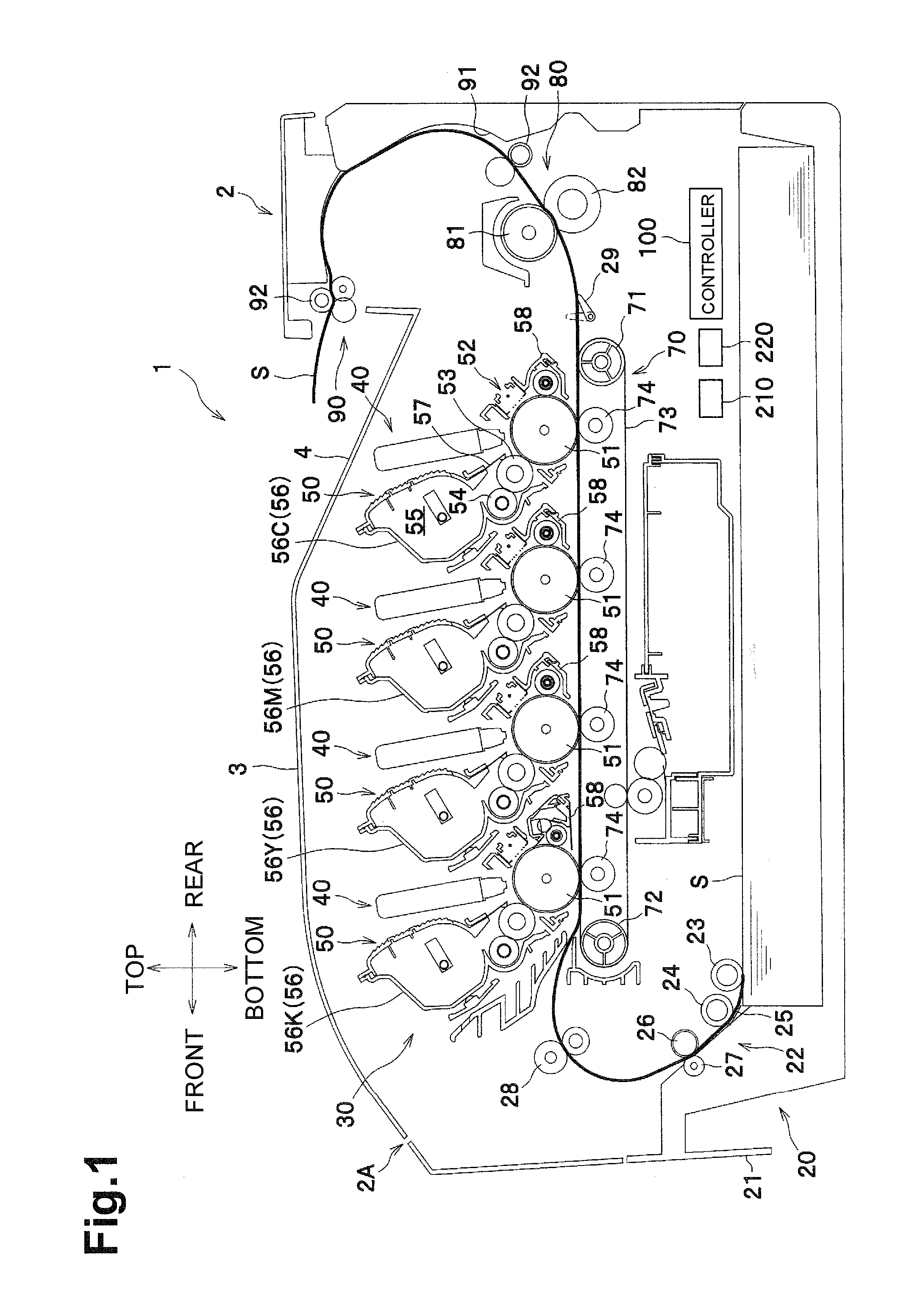
[0021]The general structure of the color printer 1 will be described with reference to FIG. 1.

[0022]For ease of discussion, in the following description, the top or upper side, the bottom or lower side, the left or left side, the right or right side, the front or front side, and the rear or rear side are used to define the various parts when the color printer 1 is disposed in an orientation in which it is intended to be used and operated. In FIG. 1, the left side is referred to as the front or front side, the right side is referred to as the rear or the rear side, the up side is referred to as the top or upper side, and the down side is referred to as the bottom or lower side.

[0023]As shown in FIG. 1, the color printer 1 includes, in a main body,...

third embodiment

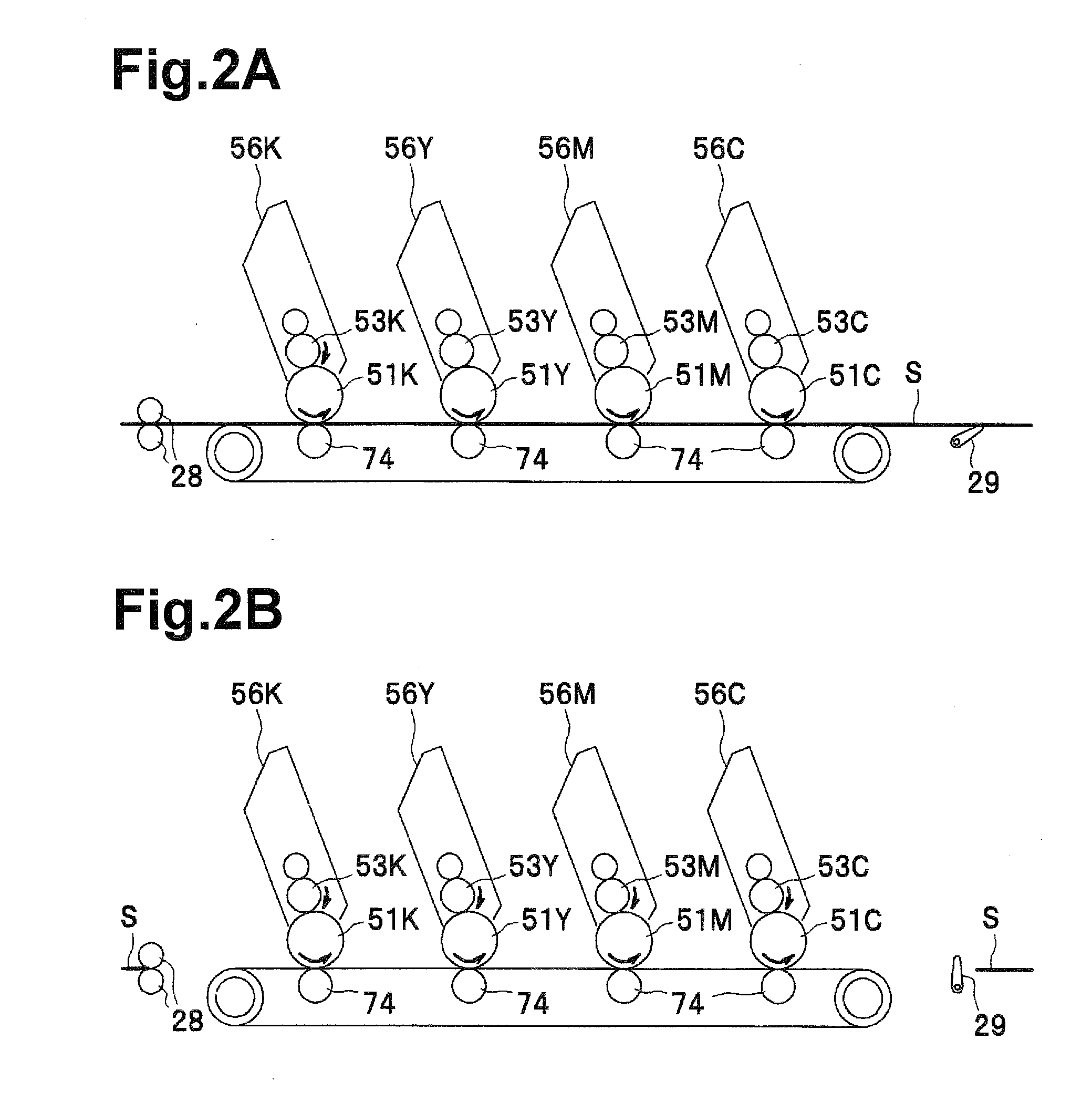
[0066]Thus, in the third embodiment, the color laser printer 1 includes second drive sources, which are not shown, and are provided in the same number as the second developing rollers 53Y, 53M and 53C, and the controller 100 controls the second drive sources to drive the second developing rollers 53Y, 53M, and 53C individually. As shown in FIG. 6, a time T1 at which the registration rollers 28 start to supply a sheet S is used as a reference point. The controller 100 controls the second drive sources individually such that, the second developing roller 53Y for yellow is temporarily rotated after a time TY has passed from the time T1, the second developing roller 53M for magenta is temporarily rotated after a time TM has passed from the time T1, and the second developing roller 53C for cyan is temporarily rotated after a time TC has passed from the time T1.

[0067]The time TY is set by adding a time required for the registration rollers 28 to feed one sheet S, a time required for the r...


PUM


Abstract

An image forming apparatus may include controls for changing a state of the developing roller from a stopped state to a rotating state. The change in state may be used to avoid deterioration of toner and/or a surface of the developing roller. Changes in state may occur at various times including at a timing corresponding to an outside of an image formation area, a timing corresponding to an inside of an image formation area and the like. In one arrangement, a first developing roller may continue to rotate (e.g., during monochrome printing), while one or more other developers are switched between a stopped state and a rotating state. Alternatively or additionally, a roller which is caused to change states may remain stopped between the timing corresponding to a rear end of an image formation area and a timing corresponding to a front end of an immediately subsequent image formation area.

Description

CROSS REFERENCE TO RELATED APPLICATION[0001]This application claims priority from Japanese Patent Application No. 2010-293222, filed on Dec. 28, 2010, the entire subject matter and contents of which are incorporated herein by reference.TECHNICAL FIELD[0002]Aspects of the disclosure relate to an image forming apparatus capable of executing both monochrome printing and color printing.BACKGROUND[0003]Some existing electrophotographic color image forming apparatuses may include photosensitive drums and developing devices in the same number as colors of toner. Each of the photosensitive drums is configured to carry an electrostatic latent image thereon. Each of the developing devices includes a developing roller configured to rotate in contact with (either directly or indirectly with toner therebetween) a corresponding one of the photosensitive drums and supply toner to the electrostatic latent image thereon. The image forming apparatus may further include a transfer belt disposed facing...

Claims


Application Information

Patent Timeline
Patent Type & Authority Applications(United States)
IPC IPC(8): G03G15/01
CPCG03G15/0136G03G15/0189G03G2215/0122G03G2215/0103G03G2215/0119
Inventor SUZUKI, YASUHIROHATTORI, YOSHITERU
Owner BROTHER KOGYO KK
Why Eureka
Try Eureka