Device and method for fish tape reel system

a technology of fish tape and reel system, which is applied in the direction of cable installation apparatus, electrical apparatus, cable laying apparatus, etc., can solve the problems of physical demands, time-consuming and laborious, and large unplanned workload, saving a lot of hard work and the need for two workers

Inactive Publication Date: 2012-07-05
ORR NISTAR
View PDF1 Cites 7 Cited by
  • Summary
  • Abstract
  • Description
  • Claims
  • Application Information

AI Technical Summary

Benefits of technology

[0020]In some embodiments, the coupler includes several arms pivotably extending from a first ring circling the guiding pipe, which is displaceable towards and away from the embracing member. The two or more arms are forced to lean on a second ring, whereas

Problems solved by technology

Manual operation of a fish tape is physically demanding, time consuming and labor intensive, and two workers are usually needed, one at each end of the conduit.
Moreover, sometimes a snagging of the fish tap

Method used


Image

  • Device and method for fish tape reel system
  • Device and method for fish tape reel system
  • Device and method for fish tape reel system

Examples


Embodiment Construction

[0037]The present invention will now be described in terms of specific example embodiments. It is to be understood that the invention is not limited to the example embodiments disclosed. It should also be understood that not every feature of the methods and systems handling the described device is necessary to implement the invention as claimed in any particular one of the appended claims. Various elements and features of devices are described to fully enable the invention. It should also be understood that throughout this disclosure, where a method is shown or described, the steps of the method may be performed in any order or simultaneously, unless it is clear from the context that one step depends on another being performed first.

[0038]Before explaining several embodiments of the invention in detail, it is to be understood that the invention is not limited in its application to the details of construction and the arrangement of the components set forth in the following descriptio...


PUM


Abstract

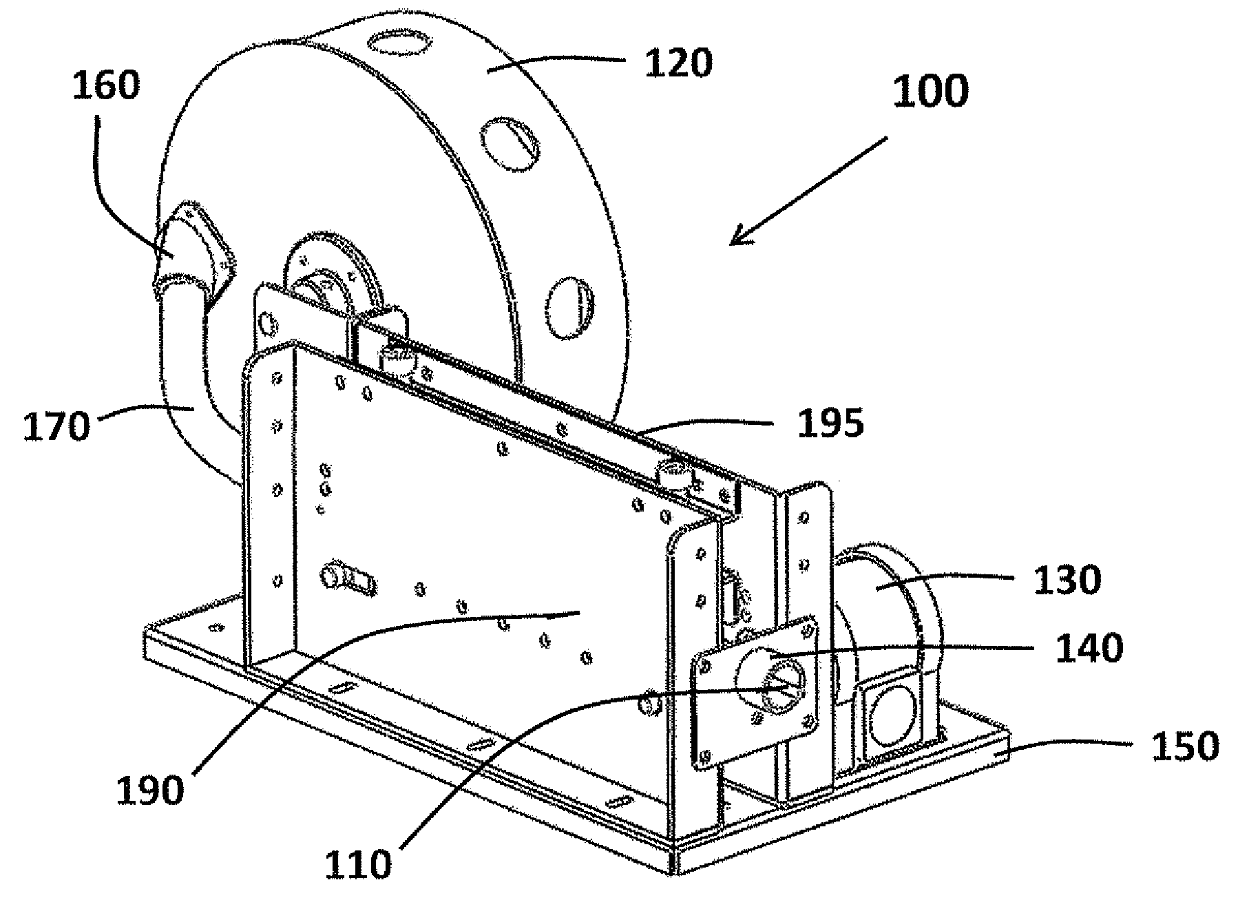
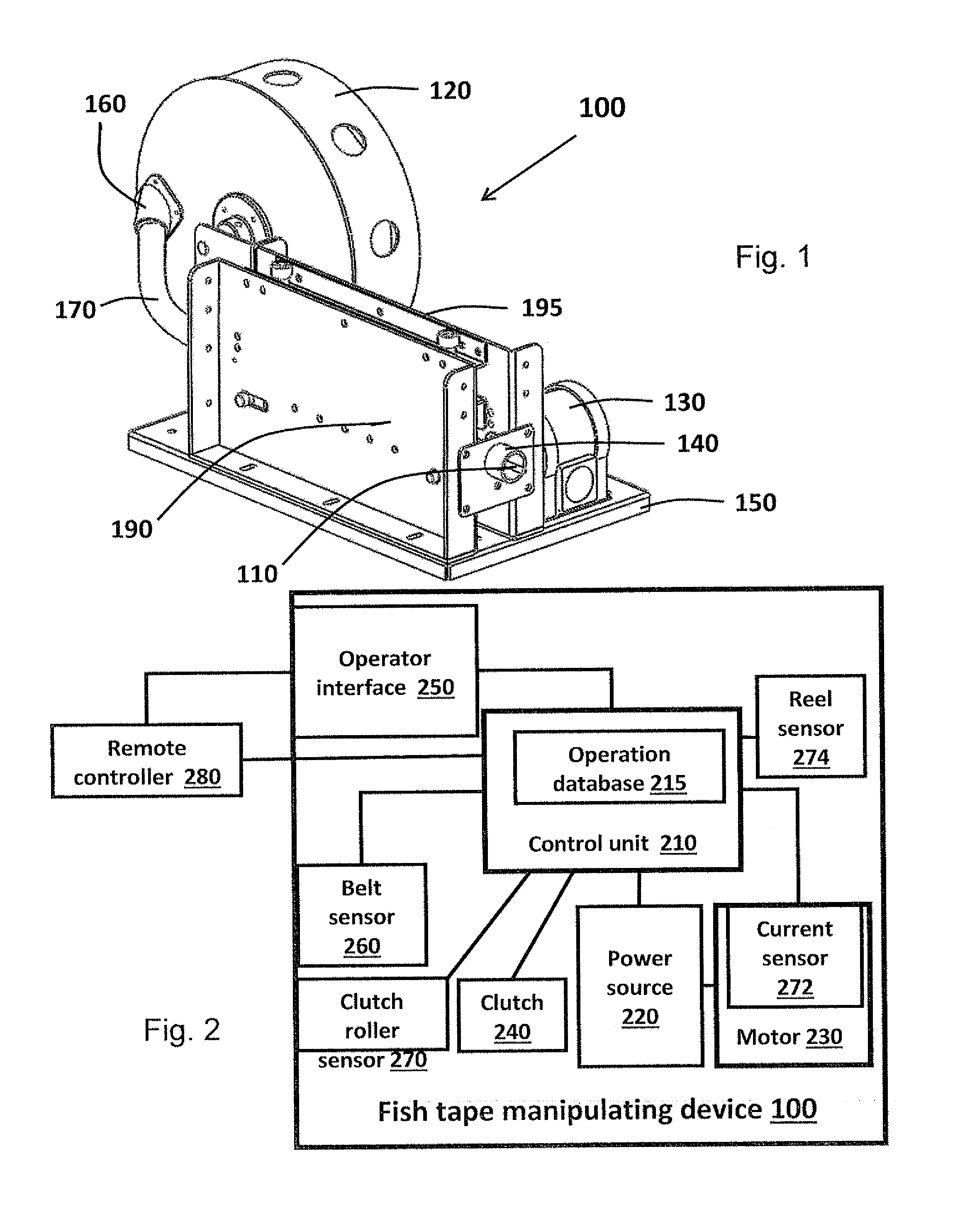
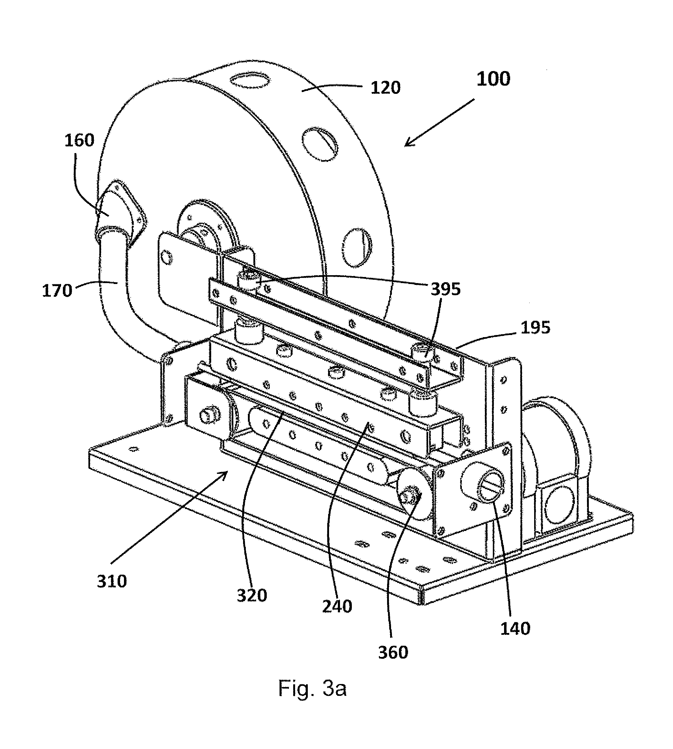
It is provided an electrically powered fish tape manipulating device. The device includes a control unit, a power source and a two-way belt system rotatable in accordance with the provided power. A segment of the fish tape is disposed forcibly on the belt such that rotating the belt system forces the fish tape to propagate accordingly. The device includes a rotatable reel assembly for receiving a length of a fish tape. Manipulation parameters include direction and speed of belt rotation, and a serial list of manipulations, defined by direction, speed and duration values. A motor receives the provided power, a gear reduces rotation speed, and drives the two-way rotating belt system. A sliding clutch having a sliding surface forces the fish tape segment to propagate whenever the belt rotates. The control unit is associated with a wireless remote controller. A conduit coupler receives the fish tape and guides it into a conduit. The coupler includes a guiding pipe for guiding the fish tape between the device and the conduit, a fastening member, and means for pressing portions of the fastening member to walls of a structure associated with the conduit, thereby connecting the guiding pipe to the conduit.

Description

BACKGROUND OF THE INVENTION[0001]1. Field of the Invention[0002]The invention is in the field of accessories for electricity and communications technicians. It deals especially with an automatic device for pushing and pulling a fish tape.[0003]2. Description of Related Art[0004]Building codes require electrical and communications wiring to be enclosed within a housing like a conduit or a pipe. Usually, the conduit is installed in the building during construction, sometimes with a drawing rope there within. For installing electrical and communication wiring, in absence of an appropriate drawing rope a fish tape is pushed along the conduit from end to end, the desired wire is coupled to the fish tape on one end, and an operator pulls the fish tape and the coupled wire from the other end.[0005]Manual operation of a fish tape is physically demanding, time consuming and labor intensive, and two workers are usually needed, one at each end of the conduit. Moreover, sometimes a snagging of ...

Claims


Application Information

Patent Timeline
IPC IPC(8): H02G1/08
CPCH02G1/085
Inventor RACHMINOV, YONAPERETS, MICHELEHAYUN, TOMER
Owner ORR NISTAR
Why Eureka
Try Eureka