Antenna mount adapter

Active Publication Date: 2012-07-05
HARRIS GLOBAL COMMUNICATIONS INC
View PDF9 Cites 1 Cited by
  • Summary
  • Abstract
  • Description
  • Claims
  • Application Information

AI Technical Summary

Benefits of technology

[0011]Advantageously, clearance openings in the bottom flange of the upper member are aligned with threaded openings provided around the perimeter of the antenna mount opening of the non-NATO type armored vehicle, and the upper member is secured to the vehicle with bolts which are inserted into the threaded openings. In the case of armored vehicles conforming to the mounting system used in the former Soviet Union, the six evenly spaced clearance openings are provided in the bottom flange of the upper member. These six clearance openings are aligned with six threaded openings provided around the perimeter of the antenna mount opening. A gasket can be placed between the flange and the vehicle to provide a water tight seal. Thereafter, and from the inside of the vehicle, the threaded end of the lower member is threaded into the upper member until the flange on the lower

Problems solved by technology

Presently, military vehicles from some of these countries are not equipped with an antenna mount opening pattern which is compatible with or configured to accept an antenna used by NATO.
In addition, armor plated vehicles which have an antenna mount opening which is not configured to meet NATO standards cannot be readily modified to accommodate an antenna mount which is designed to NATO specifications.
Such mounts normally replace the existing antenna mounts and may change the profile of the antenna mount to a significant extent.
Furthermore, such antenna mounts are not designed to withstand the forces that the antenna structure of armored military vehicles frequently experience.

Method used


Image

  • Antenna mount adapter
  • Antenna mount adapter
  • Antenna mount adapter

Examples


Embodiment Construction

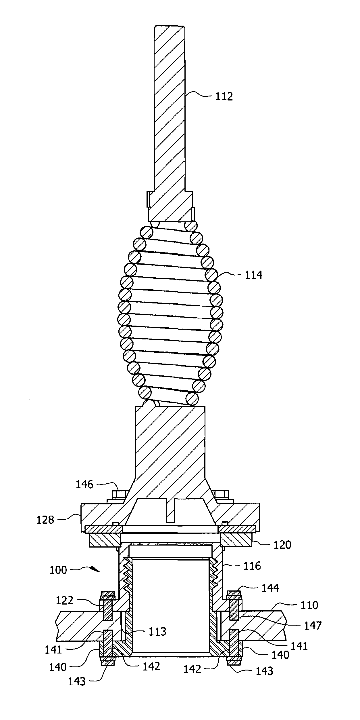
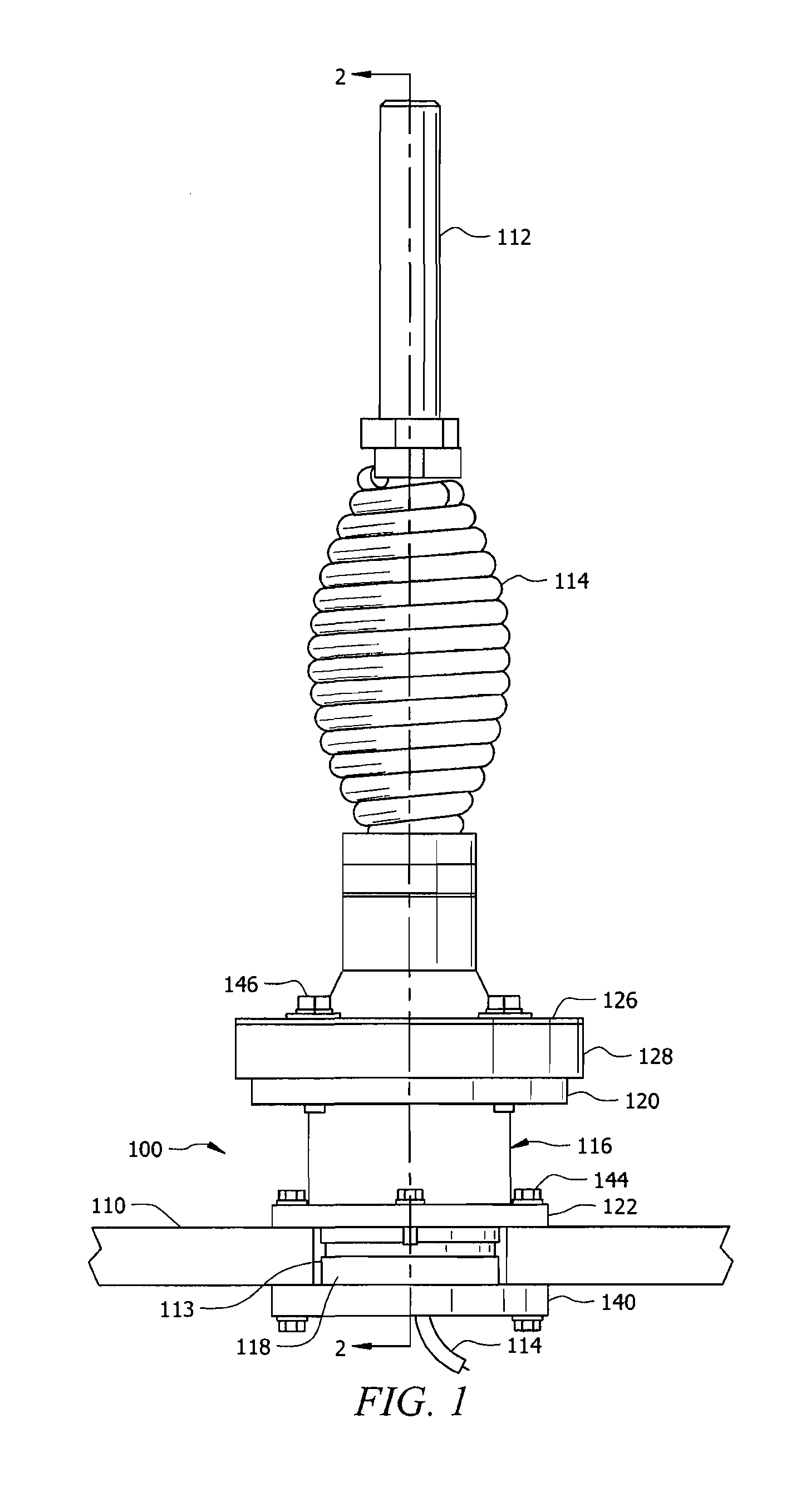
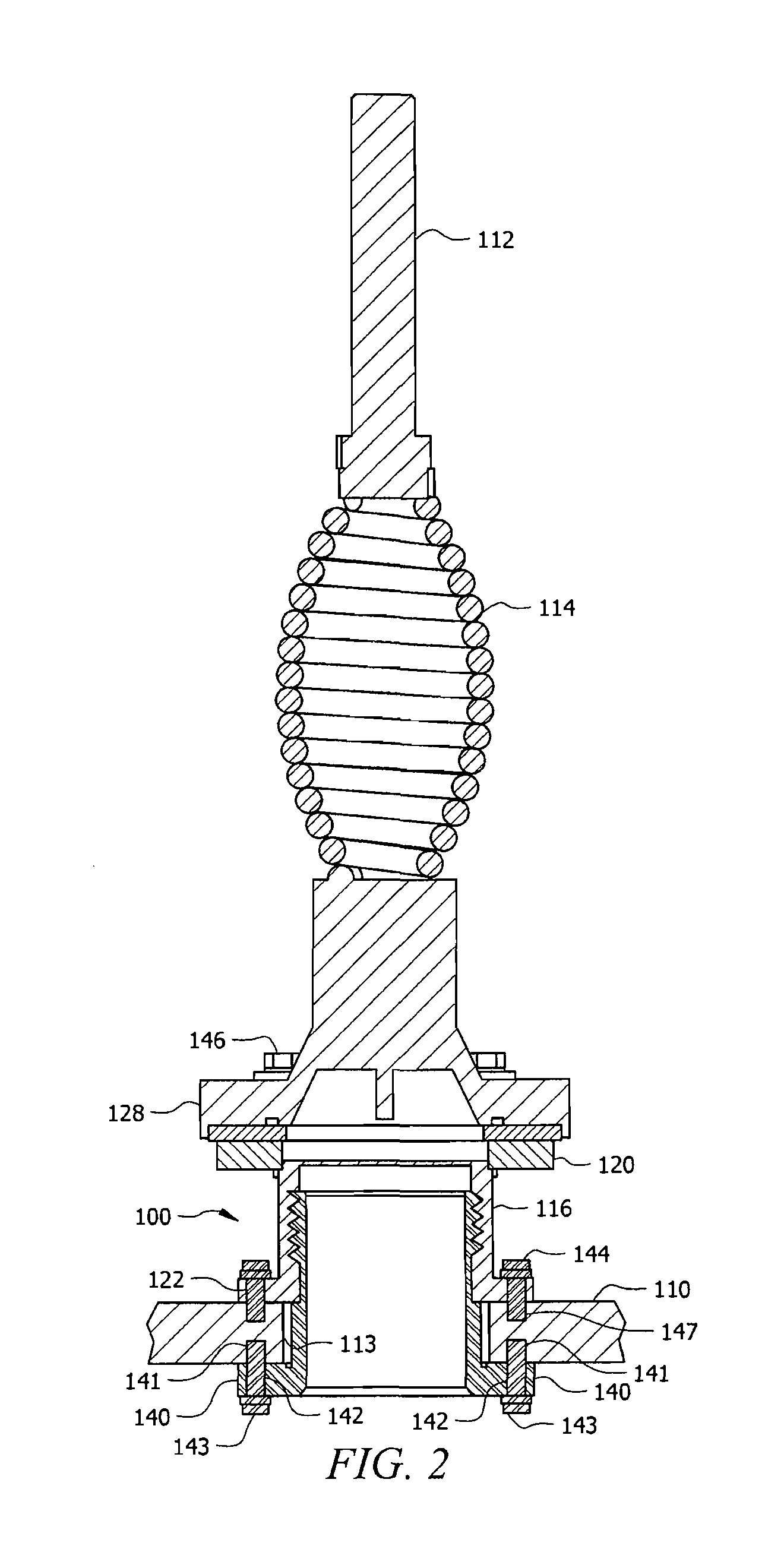
[0019]The invention concerns a rugged antenna mount adapter for mounting a first type of antenna mounting base to an existing antenna mount opening designed for a second type mounting base, different from the first type mounting base. The invention is particularly well suited for mounting an antenna having a standard NATO type antenna mounting base to an armored vehicle which does not conform to NATO antenna mount standards, regardless of the thickness of the armor on the vehicle. Examples of armored vehicles that do not conform to NATO antenna mount standards are those which have been produced for China, Russia, and the former Soviet Union. For convenience, such armored vehicles shall be referred to herein as non-NATO type armored vehicles. Also, the invention shall be described herein with reference to a style of antenna mount used by Russia and the former Soviet Union. However, it should be understood that the invention is not limited in this regard. The invention can also be use...


PUM


Abstract

The invention concerns a rugged antenna mount adapter (100) for mounting an antenna (112) used by NATO vehicles to an existing antenna mount opening (113) of a non-NATO type armored vehicle, regardless of the thickness of the armor (110) on the vehicle. The antenna mount adapter has an upper member (116) and a lower member (118). The upper member (116) has two flanges (120, 122) separated by a hollow cylindrical body (116) having internal threads (134). The top flange (120) is adapted to receive a NATO style antenna and the bottom flange (122) is adapted to be attached to the outside surface and aligned with the antenna mount opening (113) of a non-NATO type armored vehicle. The lower member (118) is a hollow cylindrical body having a flange (140) at one end and a screw thread (136) which extends along the outside surface of the cylinder at the other end. The screw thread end of the lower member is designed to screw into the upper member from the interior of the vehicle until the flange on the lower member abuts the inside wall of the vehicle.

Description

BACKGROUND OF THE INVENTION[0001]1. Statement of the Technical Field[0002]The inventive arrangement relates to antennas and more particularly to an antenna mount for use on a military vehicle.[0003]2. Description of the Related Art[0004]Radio communications between the crew of a military land vehicle with the crews of other military land vehicles, command headquarters, ground personal, and aircraft involved in a common mission is of critical importance during military operations. Also important is the ability of a military land vehicle to receive Global Positioning System information for navigational purposes.[0005]An antenna for receiving and transmitting such information is preferably mounted external to a military vehicle and is typically mounted in a separate housing. For certain applications, and particularly for military ground vehicles, the antenna mount must be a sturdy mount which can withstand substantial forces on the antenna such as occurs when the antenna contacts trees...

Claims


Application Information

Patent Timeline
IPC IPC(8): H01Q1/32
CPCH01Q1/1214
Inventor CHRIST, BARRYBUTTERBAUGH, DONALD B.HENDERSHOT, AARON K.
Owner HARRIS GLOBAL COMMUNICATIONS INC
Why Eureka
Try Eureka