Display device and display method

a display device and display method technology, applied in the field of display devices, can solve the problems of black not being fully reproduced, significant amount of power consumption waste, and significant proportion of backlight power consumption in the power consumption of the entire liquid crystal display apparatus, so as to compensate for image deterioration, uneven brightness, and decrease contrast

Active Publication Date: 2012-07-05
PANASONIC INTELLECTUAL PROPERTY MANAGEMENT CO LTD
View PDF3 Cites 24 Cited by
  • Summary
  • Abstract
  • Description
  • Claims
  • Application Information

AI Technical Summary

Benefits of technology

[0019]The present invention can compensate for image deterioration caused by unevenness in brightness and partial decrease of contrast due to physical limitations of a display device, using human visual characteristics, in a local dimming technique of the display apparatus.

Problems solved by technology

However, the proportion of backlight power consumption occupies in the power consumption of the entire liquid crystal display apparatus is significant, and a significant amount of power is consumed wastefully.
Further, the liquid crystal panel cannot completely block light, and therefore black cannot be fully reproduced and a display image has lower contrast due to impure black.
Although there is a technique of dynamically changing the light emission brightness of a backlight to solve these problems, if there is a little bright part on a screen to display a video signal, the light emission brightness of backlight cannot be decreased, and therefore it is not possible to provide a great effect.
However, this local dimming generally has a problem that changing the light emission brightness of backlight per light emitting area causes change of brightness in a display image.
Illumination light emitted by the backlight is diffused in a wide range, and therefore accurately predicting the light emission brightness of backlight per pixel not only requires a significant amount of computation but also actually has a great difficulty in terms of an algorithm and is not easy to carry out.
However, theoretically, this technique is feasible, if cost and labor are spent.
However, it is not physically possible to set the transmittance to 1 or more, and therefore the transmittance actually needs to be limited to a predetermined maximum transmittance.
Therefore, the brightness decreases in pixels at ends of a high brightness area, thereby causing image deterioration such as unevenness in brightness, a decrease of contrast and halo (shade of a low brightness object produced in high brightness areas around a low brightness object).
However, the minimum transmittance has a limit, and it is not physically possible to further decrease and correct transmittance, and therefore the transmittance actually needs to be limited to the minimum transmittance.
As a result, the brightness of pixels at ends of black areas increases, thereby causing image deterioration such as unevenness in brightness, impure black, a decrease of contrast and halo (blur of a high brightness object produced in black areas around a high brightness object).

Method used


Image

  • Display device and display method
  • Display device and display method
  • Display device and display method

Examples


embodiment 1

[0061]Next, an image display apparatus according to Embodiment 1 will be described with reference to the drawings.

[0062]FIG. 1 is a block diagram illustrating a configuration of the image display apparatus according to Embodiment 1.

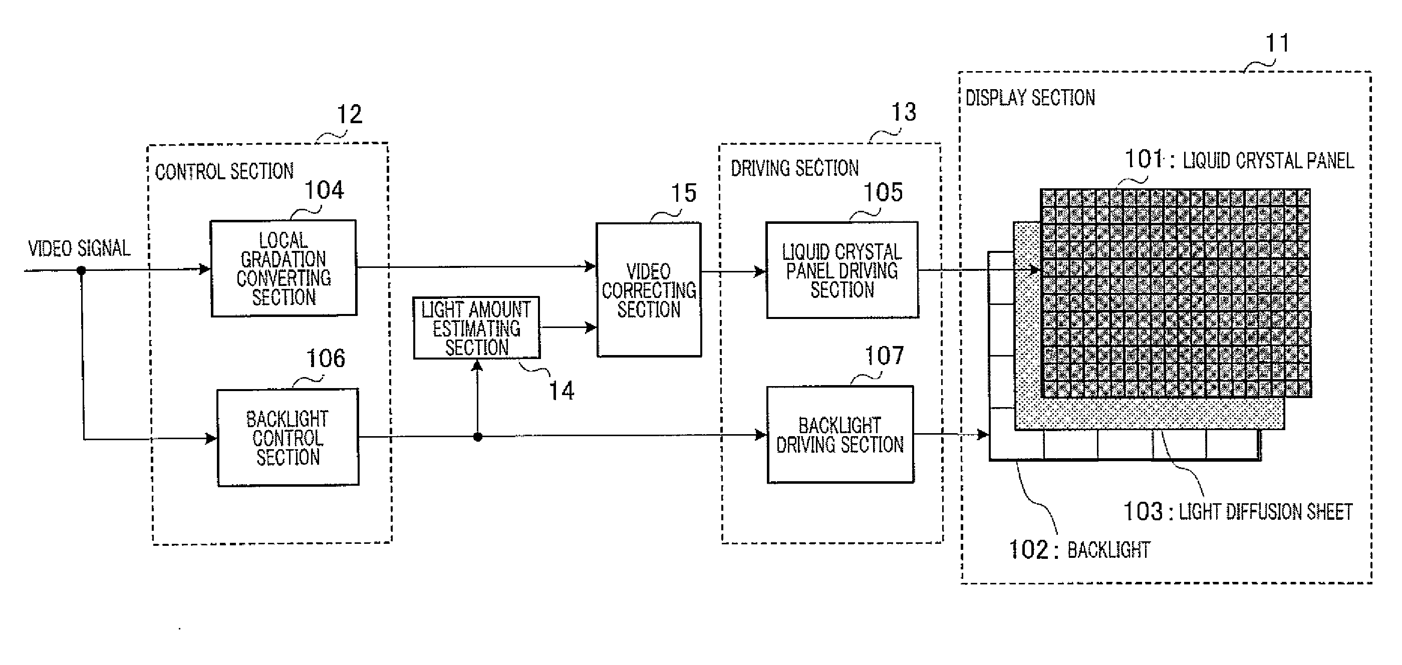
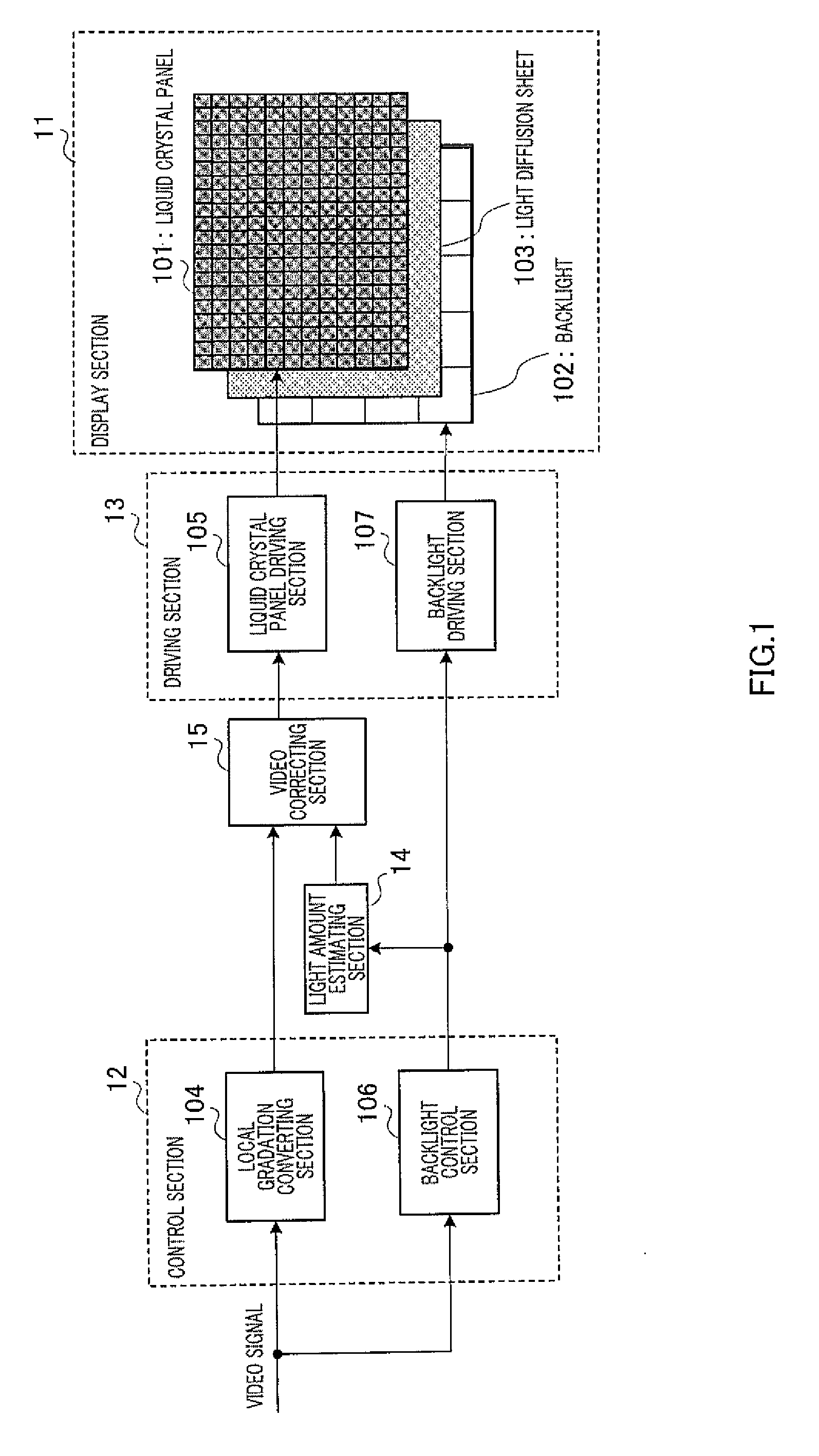
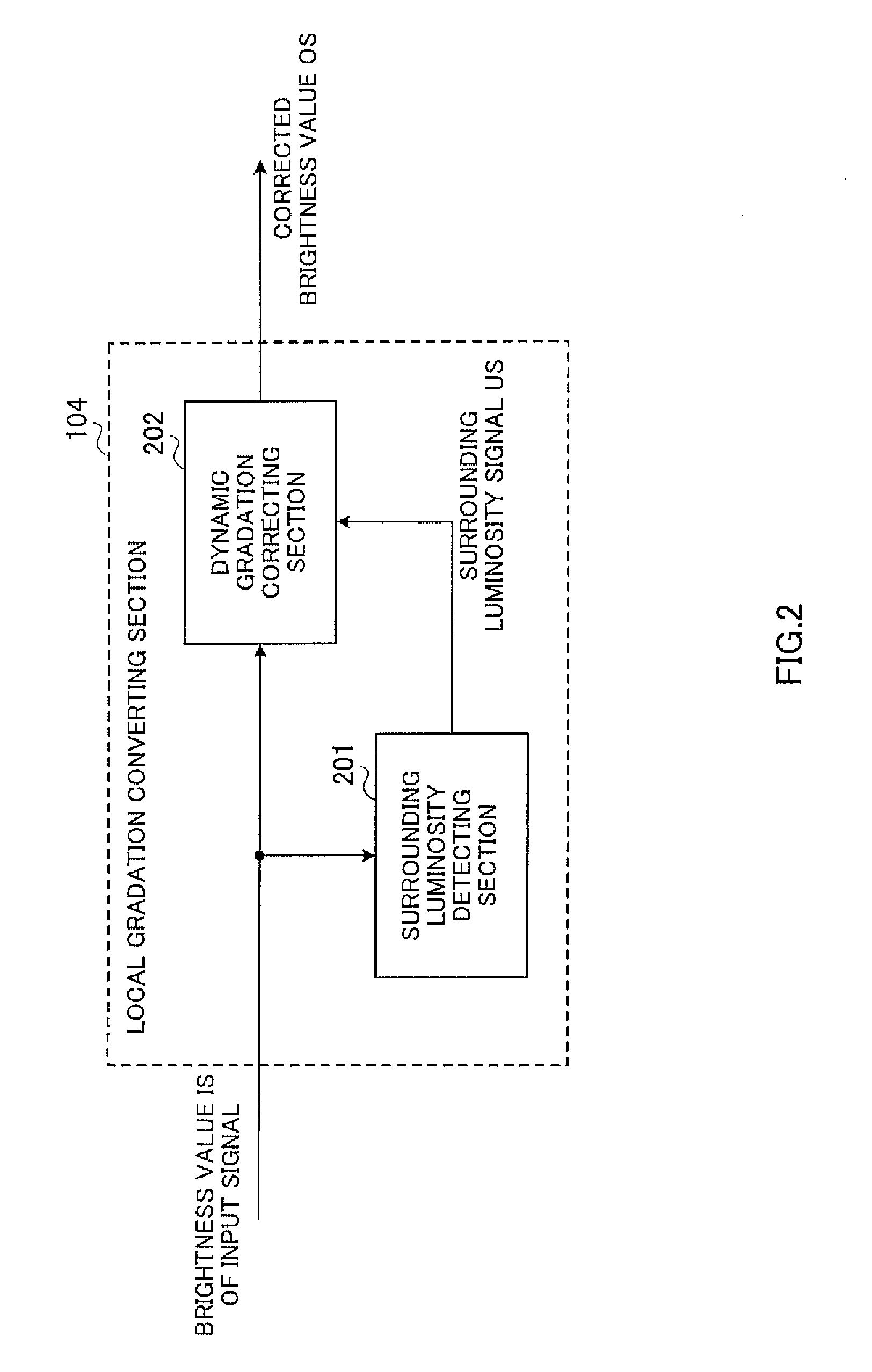
[0063]The image display apparatus according to Embodiment 1 has display section 11, control section 12, driving section 13, light amount estimating section 14 and video correcting section 15. Further, display section 11 has liquid crystal panel 101, backlight 102 and light diffusion sheet 103. Further, control section 12 has local gradation converting section 104 and backlight control section 106. Furthermore, driving section 13 has liquid crystal panel driving section 105 and backlight driving section 107.

[0064]101>

[0065]Liquid crystal panel 101 modulates the illumination light radiated on its back face, according to a control signal input from liquid crystal panel driving section 105 to display an image on a screen which is the surface of liquid crystal...

embodiment 2

[0147]Next, an image display apparatus according to Embodiment 2 will be described with reference to the drawings.

[0148]FIG. 8 is a block diagram illustrating a configuration of the image display apparatus according to Embodiment 2.

[0149]The image display apparatus according to Embodiment 2 has display section 11, control section 12 and driving section 13. Further, display section 11 has liquid crystal panel 101, backlight 102 and light diffusion sheet 103. Further, control section 12 has local gradation converting section 104 and backlight control section 106. Furthermore, driving section 13 has liquid crystal panel driving section 105 and backlight driving section 107.

[0150]That is, the image display apparatus according to Embodiment 2 differs from the image display apparatus according to above Embodiment 1 in that light amount estimating section 14 and video correcting section 15 are not provided.

[0151]101>

[0152]Liquid crystal panel 101 modulates illumination light radiated on it...

embodiment 3

[0193]Hereinafter, Embodiment 3 will be described.

[0194]In Embodiment 2, the gradation characteristics in dynamic gradation correcting section 202 in local gradation converting section 104 are set based on the straight line connecting the “” symbols in FIG. 3, that is, a straight line of the inclination 1 passing the origin. This setting provides characteristics of enhancing only local contrast without changing a visual brightness.

[0195]However, when local dimming control is performed, a brightness value which varies per light emitting area of backlight 102 is set based on the brightness value of an input video signal. More specifically, a lower brightness value than the brightness value of the input video signal is set.

[0196]Therefore, when the transmittance of liquid crystal panel 101 is set based on the brightness value of the input video signal, the brightness value of the light emitting area of backlight 102 is lower, and therefore the brightness value displayed on liquid crys...


PUM


Abstract

Disclosed is a display device capable of compensating unevenness in brightness caused by physical restrictions of a display device or degradation in image quality caused by a partial reduction in contrast occurring in the local dimming technology using human visual characteristics. A liquid crystal panel (101) modulates illuminating light in accordance with the transmittance, and displays images on a screen. A backlight (102) emits the illuminating light to the liquid crystal panel (101) such that amounts of the illuminating light differ for each light emitting area of the screen. A backlight control unit (106) controls emission brightness of the backlight (102) for each light emitting area. A local gradation converting unit (104) performs gradation conversion on an image signal, and acquires a brightness value for each pixel after the conversion. A backlight driving unit (107) controls the transmittance for each pixel on the basis of the acquired brightness values after the conversion. The local gradation converting unit sets conversion characteristics for pixels to be processed in the image signal such that the brightness values of the pixels to be processed are low as the lightness of the periphery of the pixels to be processed is high, and performs gradation conversion using the set conversion characteristics.

Description

TECHNICAL FIELD[0001]The present invention relates to a display apparatus which uses, for example, liquid crystal and a display method, and more particularly, relates to local dimming technique of a backlight light source of a transmissive liquid crystal display apparatus.BACKGROUND ART[0002]The liquid crystal display apparatus of a transmissive type radiates illumination light on a back face of a liquid crystal display element (hereinafter “liquid crystal panel”) by means of an illuminating apparatus (hereinafter “backlight”) and modulates the transmittance of illumination light by means of the liquid crystal display element and changes brightness to display an image. Although some projectors use reflective liquid crystal display elements, the only difference from the transmissive type is that transmittance changes to reflectivity.[0003]A liquid crystal display apparatus generally emits light on the entire screen at a maximum brightness, irrespective of the display content of an in...

Claims


Application Information

Patent Timeline
Patent Type & Authority Applications(United States)
IPC IPC(8): G09G5/10
CPCG02F1/1336G02F2001/133601G09G3/2051G09G3/3426G09G2360/16G09G2310/0232G09G2320/0233G09G2320/0238G09G2320/0646G09G3/3611G02F1/133601
Inventor YAMASHITA, HARUOITO, TAKESHI
Owner PANASONIC INTELLECTUAL PROPERTY MANAGEMENT CO LTD
Why Eureka
Try Eureka