Lighting device, display device and television device

a technology of display device and light source, which is applied in the field of light source device, display device, and television device, can solve the problems of increasing production cost and length limit of led board

Inactive Publication Date: 2014-10-16
SHARP KK
View PDF7 Cites 9 Cited by
  • Summary
  • Abstract
  • Description
  • Claims
  • Application Information

AI Technical Summary

Benefits of technology

[0019]According to this invention, a lighting device and the like in which uneven brightness due to a connector that is arranged on a light source board is less likely to occur can be provided.

Problems solved by technology

However, there is a length limit for the LED boards that can be produced by an existing facility.
Establishing new facilities to produce LED units for larger lighting devices increases the production cost, which is not preferable.

Method used


Image

  • Lighting device, display device and television device
  • Lighting device, display device and television device
  • Lighting device, display device and television device

Examples


first embodiment

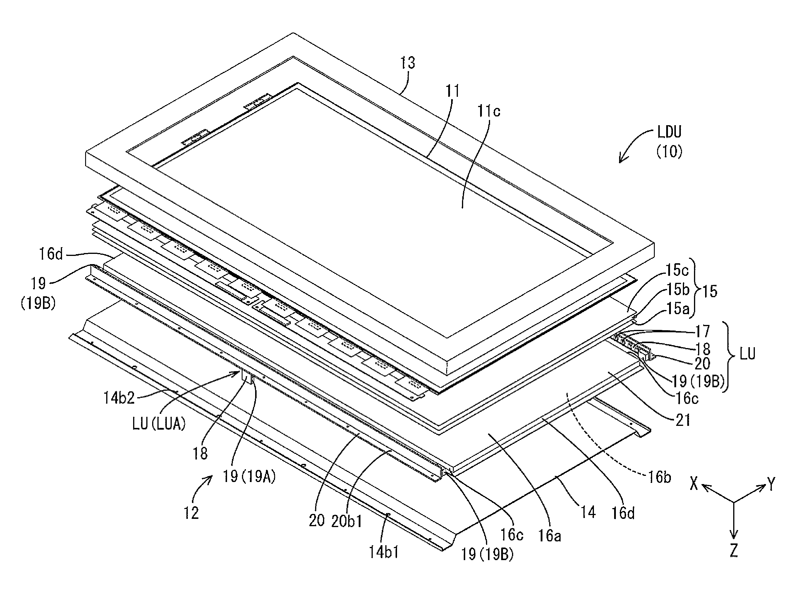
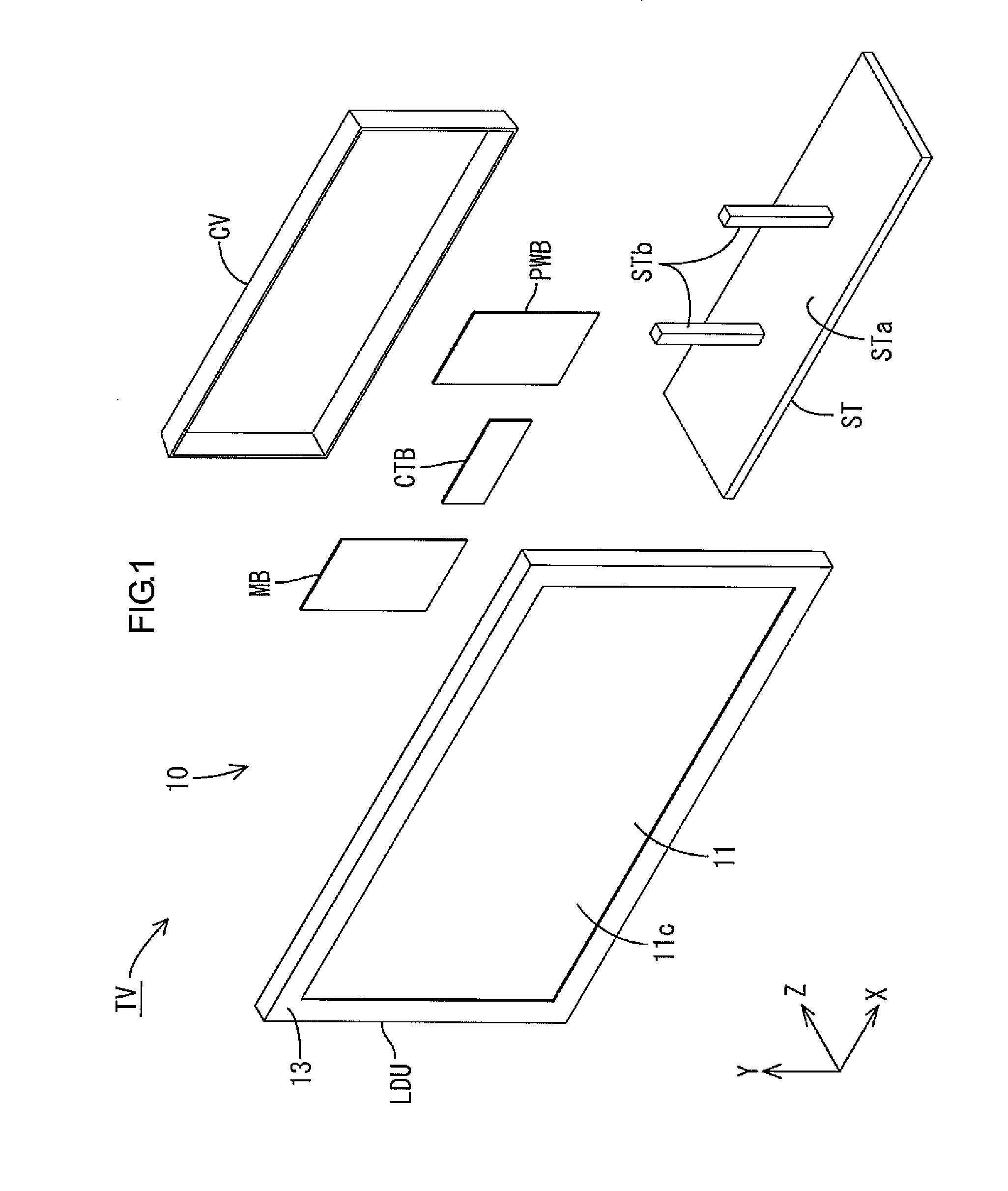
[0033]A first embodiment of this invention will be described with reference to FIGS. 1 to 8. According to this embodiment, a television device TV, a liquid crystal display device 10, and a lighting device 12 will be described. X-axis, Y-axis and Z-axis are indicated in some drawings. The axes in each drawing correspond to the respective axes in other drawings. The upper side and the lower side in FIG. 4 correspond to a front side (a display side) and a rear side (a back side), respectively.

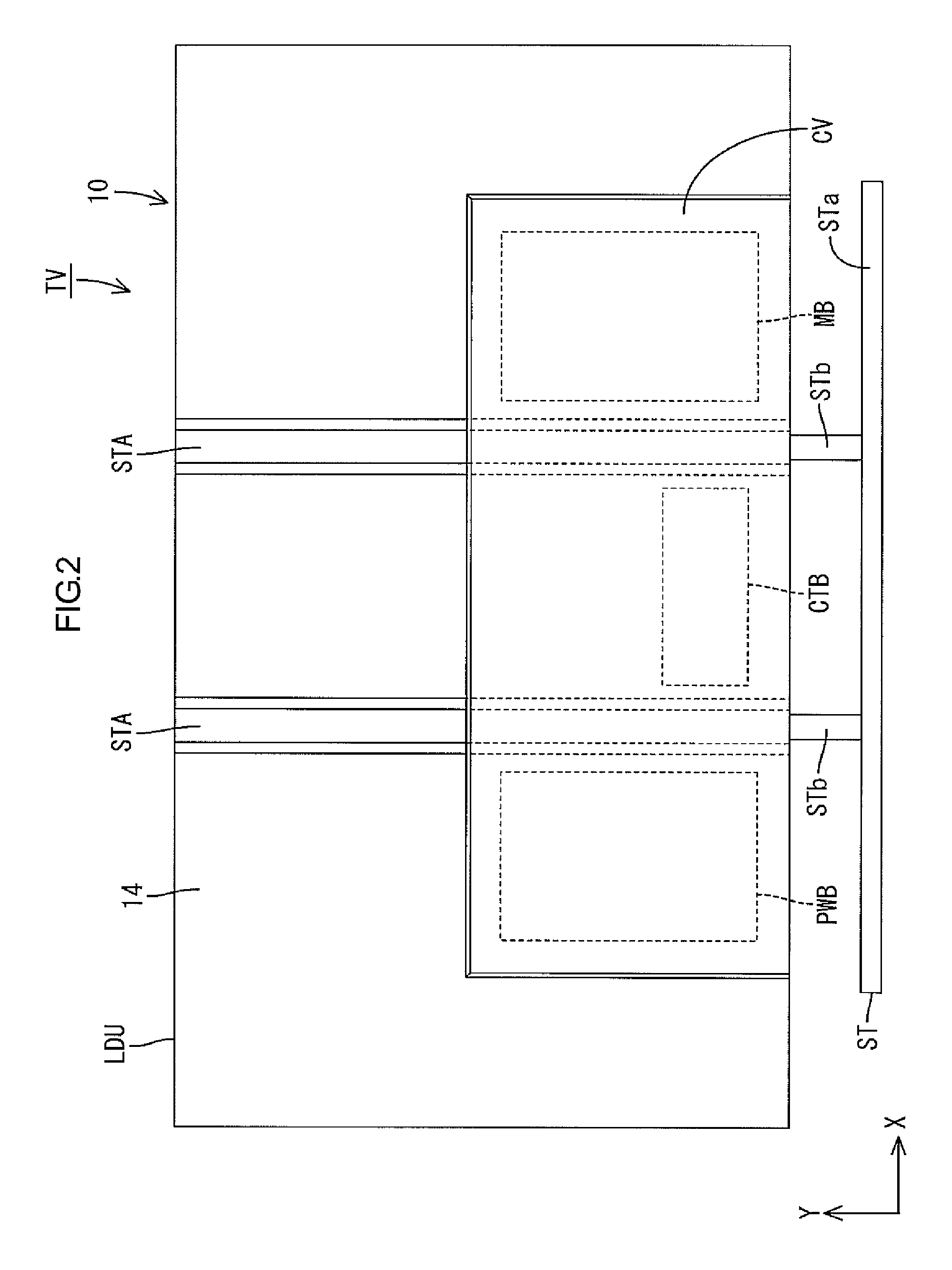
[0034]FIG. 1 is an exploded perspective view illustrating a general configuration of the television device TV according to the first embodiment of this invention. FIG. 2 is a back view of the television device TV. As illustrated in FIG. 1, the television device TV according to this embodiment includes a liquid crystal display unit LDU, boards PWB, MB, and CTB, a cover CV, and a stand ST. The boards PWB, MB, and CTB are attached on a rear side (a back side) of the liquid crystal display unit LDU. T...

second embodiment

[0076]A second embodiment according to this invention will be described with reference to FIGS. 9 to 11. The same components will be indicated by the same symbols as the first embodiment and will not be described. FIG. 9 is an explanatory view schematically illustrating an arrangement of the LED units LU and the reflection sheet 21 included in a lighting device according to the second embodiment. FIG. 10 is a plan view of an LED unit LUA2. FIG. 11 is a plan view of an LED unit LUA3. The basic configuration of the lighting device of this embodiment is similar to that of the first embodiment. However, configurations (types) of the LED units LU included in the lighting device of this embodiment are different from those of the first embodiment. The LED units LU included in this embodiment will be mainly described.

[0077]As illustrated in FIG. 9, in the lighting device according to this embodiment, similar to the first embodiment, three LED units LU are arranged along each long-side end s...

third embodiment

[0083]A third embodiment according to this invention will be described with reference to FIG. 12. FIG. 12 is an explanatory view schematically illustrating an arrangement of the LED unit LU and the reflection sheet 21 included in a lighting device in the third embodiment. The basic configuration of the lighting device of this embodiment is the same as that in the first embodiment. However, in the lighting device according to this embodiment, all of the LED units have the same structure (a type). Hereinafter, the LED units LU included in this embodiment will be mainly described.

[0084]As illustrated in FIG. 12, similar to the first embodiment, three LED units LU are arranged along each long-side end surface 16c (see the first embodiment) of the light guide plate 16 in the lighting device of this embodiment. The three LED units LU are arranged in line and opposite each end surface 16c. The in-line three LED units LU are all the same LED units LUA2 (refers to the second embodiment). Six...


PUM


Abstract

A lighting device 10 according to this invention includes a light guide plate 16, a reflection sheet 21, and a light source unit LU. The light guide plate 16 is a plate-like member and includes a light entrance surface 16c through which light enters and a light exit surface 16a through which the light in the light guide plate 16 from the light entrance surface 16c exits. The reflection sheet 21 is arranged such that a front surface 21a thereof is on a rear plate surface 16b of the light guide plate 16 and such that an end portion 211 of the reflection sheet 21 is located more to an outer side than the light entrance surface 16c. The light source unit LU includes a light source board 18, a plurality of light sources 17, and a connector 19A configured to relay an electric power supply to the light sources 17. The light sources 17 and the connector 19A are mounted on the light source board 18 such that the light sources 17 are opposite the light entrance surface 16c and the connector 19A is located on a rear surface 21b side of the end portion 211 of the reflection sheet 21.

Description

TECHNICAL FIELD[0001]This invention relates to a lighting device, a display device, and a television device.BACKGROUND ART[0002]A liquid crystal panel is used for a display device such as a television device, a mobile phone, and a handheld terminal. The liquid crystal panel requires light to display an image. Therefore, as disclosed in Patent Document 1, the display device includes a lighting device (or a backlight device) together with the liquid crystal panel. The lighting device that is arranged on a back side of the liquid crystal panel emits planar light toward a back surface of the liquid crystal panel.[0003]As disclosed in Patent Document 1, an edge-light type (or side-light type) lighting device including a light guide plate and a light source unit is known. The light guide plate is a transparent plate-like member. The light source unit is arranged opposite an end surface of the light guide plate. As a light source unit, a unit including multiple LEDs that are mounted on a l...

Claims


Application Information

Patent Timeline
Patent Type & Authority Applications(United States)
IPC IPC(8): F21V8/00
CPCG02B6/009G02B6/0068G02B6/0083G02B6/0091G02F1/133615G02F1/133612H04N5/64
Inventor OKA, HIDEKAZU
Owner SHARP KK
Why Eureka
Try Eureka