Light source unit, lighting device, display device and television receiver

Inactive Publication Date: 2012-11-08
SHARP KK
View PDF7 Cites 10 Cited by
  • Summary
  • Abstract
  • Description
  • Claims
  • Application Information

AI Technical Summary

Benefits of technology

[0020]According to the present invention, a light source unit that achieves wide color reproduction range and in which uneven brightness and colo

Problems solved by technology

This may cause uneven brig

Method used


Image

  • Light source unit, lighting device, display device and television receiver
  • Light source unit, lighting device, display device and television receiver
  • Light source unit, lighting device, display device and television receiver

Examples


Example

[0029]A first embodiment according to the present invention will be described with reference to FIGS. 1 to 4. An X axis, a Y-axis and a Z-axis are described in a part of the drawings, and a direction of each axial direction corresponds to a direction described in each drawing. An upper side in FIG. 3 corresponds to a front-surface side and a lower side in FIG. 3 corresponds to a rear-surface side.

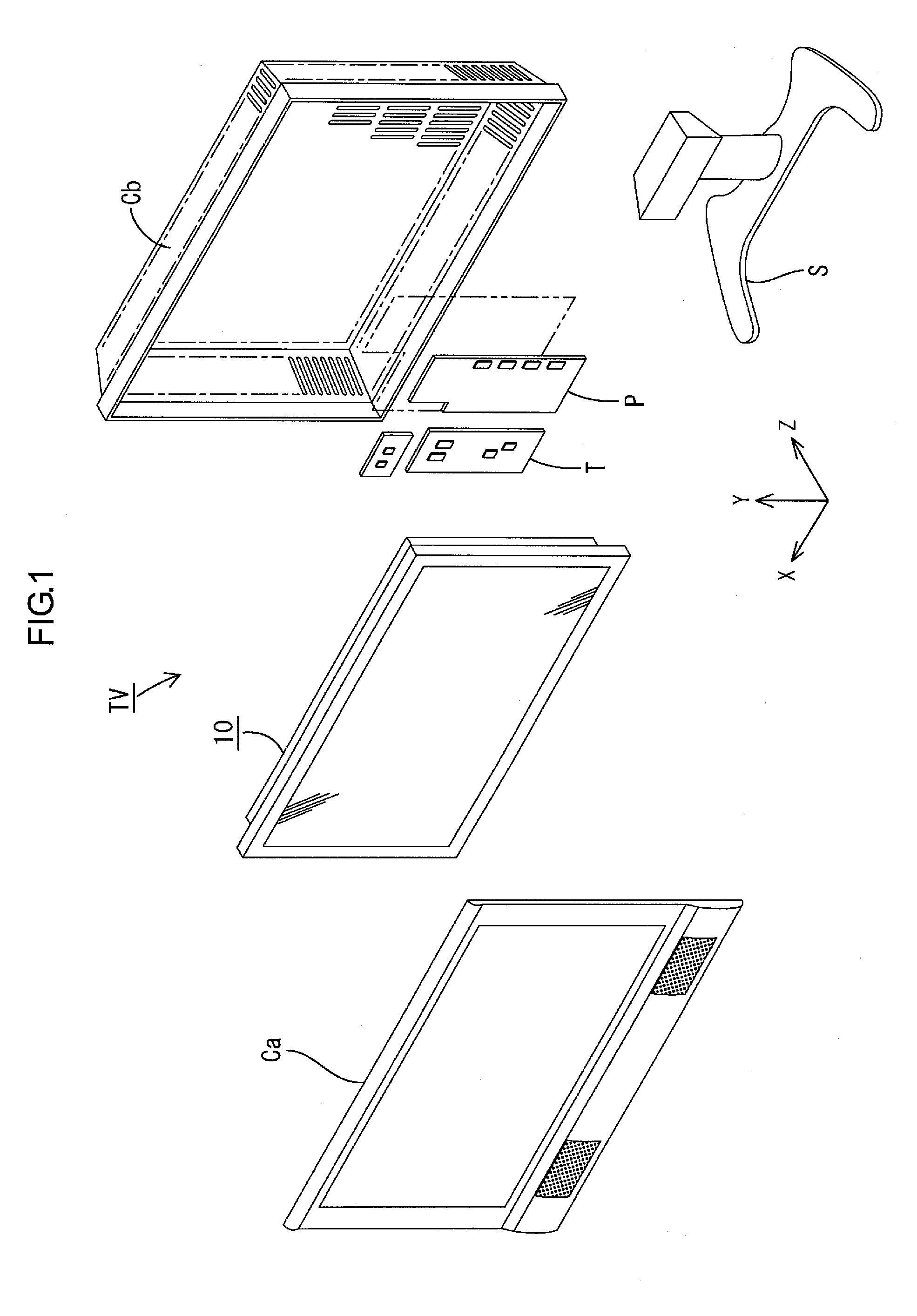
[0030]As illustrated in FIG. 1, the television receiver TV of the present embodiment includes the liquid crystal display device 10, front and rear cabinets Ca, Cb which house the liquid crystal display device 10 therebetween, a power source P, a tuner T and a stand S.

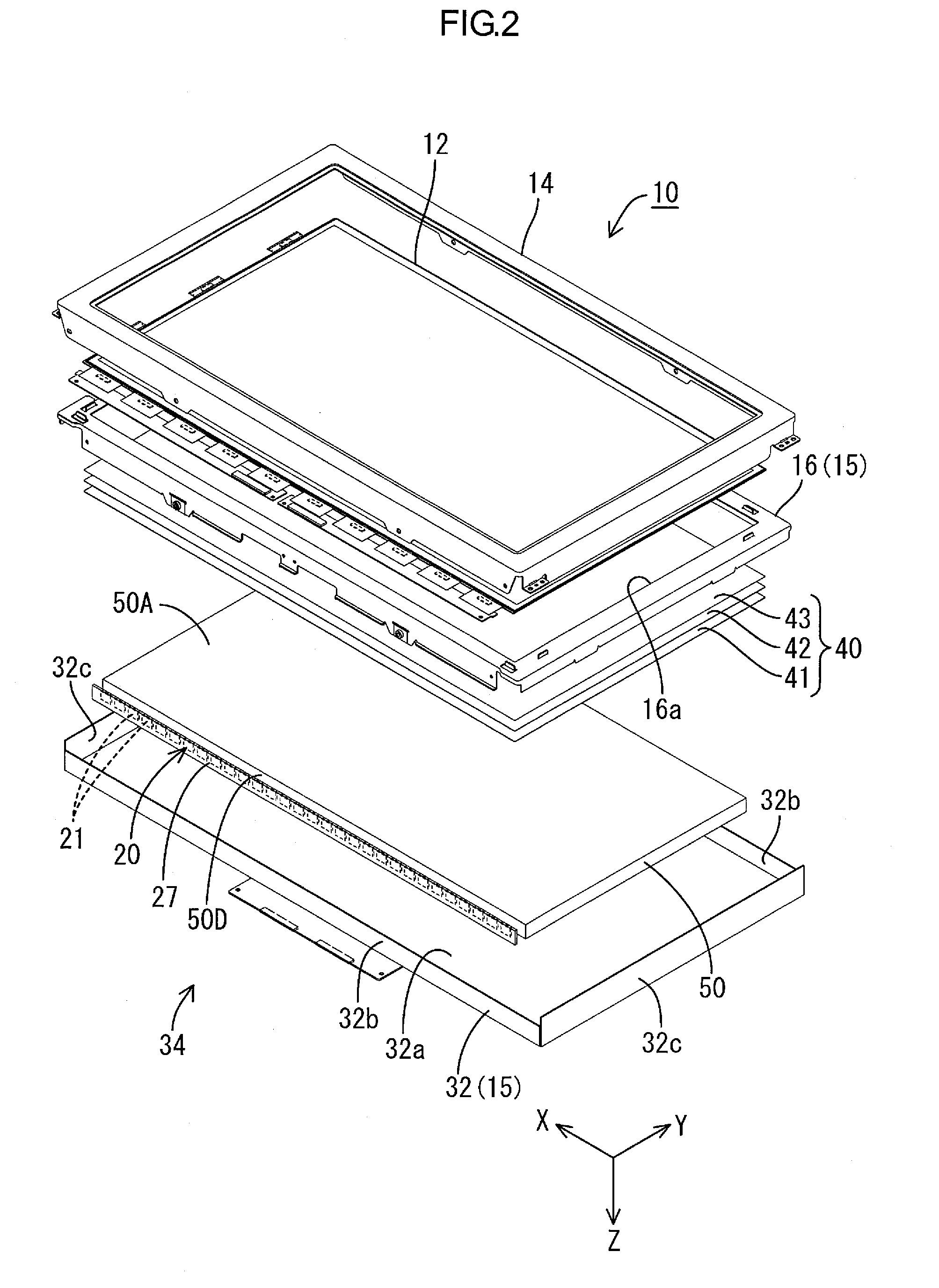
[0031]FIG. 2 illustrates an exploded perspective view of the liquid crystal display device 10. An upper side in FIG. 2 corresponds to a front-surface side and a lower side in FIG. 2 corresponds to a rear-surface side. An entire shape of the liquid crystal display device 10 is a landscape rectangular. As illustrated in FIG. 2, t...

Example

Second Embodiment

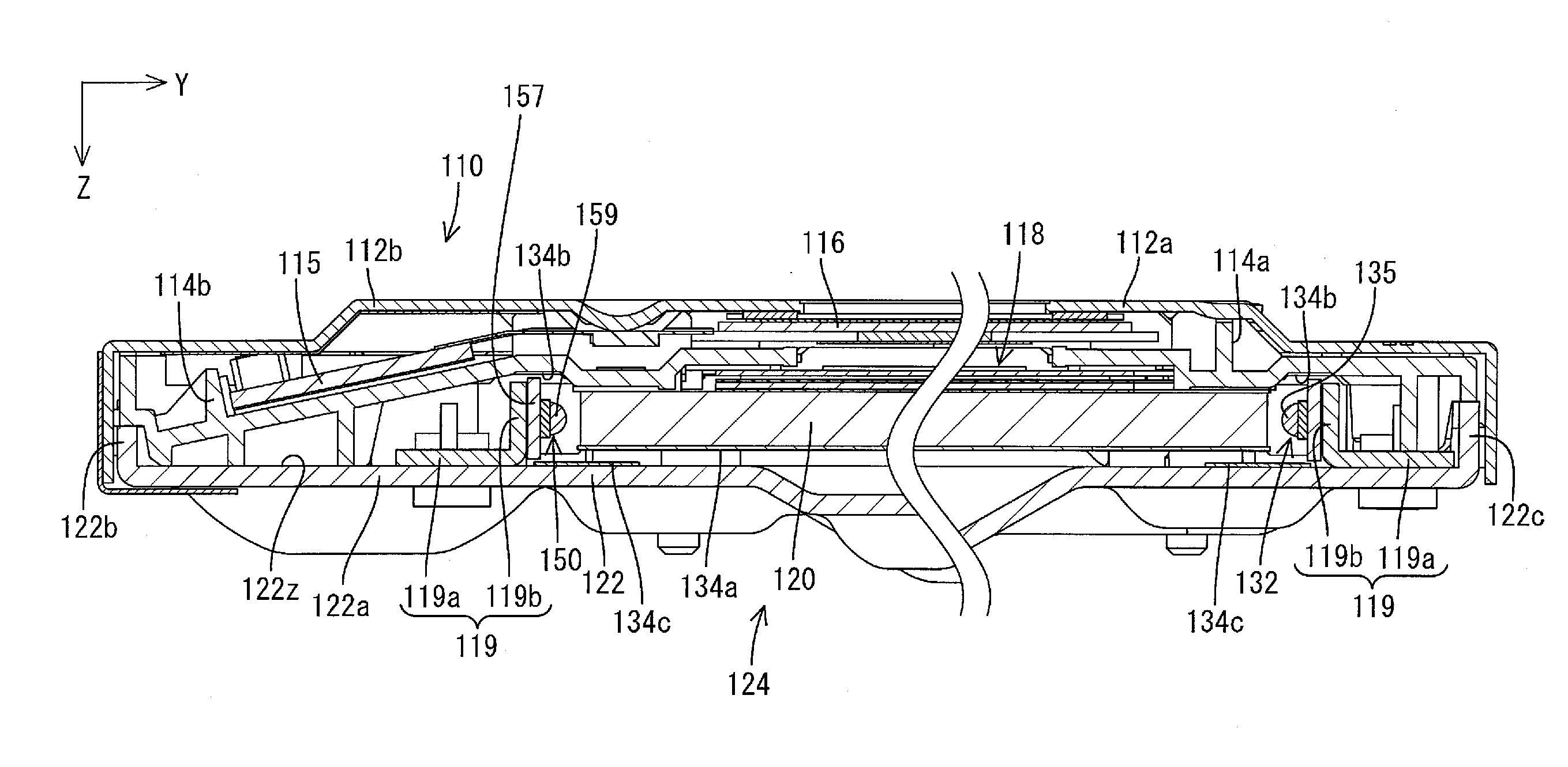
[0073]A second embodiment according to the present invention will be explained with reference to FIGS. 5 to 7. In the second embodiment, a liquid crystal display device 110 includes components different from the first embodiment. The construction, operations and effects as same as the first embodiment will not be explained.

[0074]FIG. 5 illustrates an exploded perspective view of the liquid crystal display device 110 according to the present embodiment. An upper side in FIGS. 5 and 6 corresponds to a front-surface side and a lower side in FIGS. 5 and 6 corresponds to a rear-surface side. An entire shape of the liquid crystal display device 110 is a landscape rectangular. As illustrated in FIG. 5, the liquid crystal display device 110 includes a liquid crystal panel 116 as a display panel, and a backlight unit 124 as an external light source. The liquid crystal panel 116 and the backlight unit 124 are integrally held by a top bezel 112a, a bottom bezel 112b, side bez...

Example

Third Embodiment

[0085]An LED unit 220 according to a third embodiment of the present invention will be explained with reference to FIG. 8. In the LED unit 220 of the present embodiment, an arrangement direction of the light source sets 21 is different from that of the first embodiment. In the present embodiment, the first light source 22 and the second light source 26 in each of the light source sets 21 are arranged in the same direction (X-axis direction) as the arrangement direction of the light source sets 21 on an LED board 227. With such an arrangement of the light source sets 21, a width of the LED board 227 (a length of the LED board 227 in the Z-axis direction) can be smaller than the widths of the LED boards 27 and 157.

[0086]In the present embodiment, in the two adjacent light source sets 21 (for example, 21C and 21D), the first light source 22 (22D) in one of the light source sets 21 (21D) and the second light source 26 (26C) in the other one of the light source sets 21 (...


PUM


Abstract

A light source unit in which color reproduction range is widened and uneven brightness and color unevenness are less likely to occur is provided. The light source unit includes light source sets 21 each of which includes a first light source 22 and a second light source, and an LED board 27 on which the sets 21 are arranged. The first source 22 includes a first LED chip 23 configured to emit at least a color of light of red, green or blue and phosphors excited by the light to emit light, colors of which are different from the color of the light from the chip 23. The second source 26 is configured to emit at least a color of light of cyan, magenta or yellow. The first source 22A in one of the adjacent sets and the second source 26B in another one of the adjacent sets are arranged adjacent to each other in an arrangement direction in which the adjacent sets are arranged.

Description

TECHNICAL FIELD[0001]The present invention relates to a light source unit, a lighting device, a display device and a television receiver.BACKGROUND ART[0002]In recent years, a type of an image display device including a television receiver has been shifted from a conventional CRT display device to a thin display device using a thin display element such as a liquid crystal panel and a plasma display. An image display device disclosed in Patent Document 1 has been known. The image display device includes a liquid crystal panel that includes a color filter and a lighting device that is configured to illuminate the liquid crystal panel with light. The lighting device includes a unit (light source unit) that is configured with a base board and a plurality of LEDs arranged on the base board. The lighting device illuminates the liquid crystal panel with light and the light transmits through the liquid crystal panel and subsequently passes through the color filter. The color filter includes...

Claims


Application Information

Patent Timeline
IPC IPC(8): F21V9/08H04N3/10G02F1/13357F21V5/04F21V8/00
CPCG02B6/003G02B6/0068G02B6/0073G02F1/133603H01L33/50G02F1/133617G02F1/133621H01L25/0753G02F1/133615H01L2924/0002H01L2924/00
Inventor TAKANO, YUYA
Owner SHARP KK
Why Eureka
Try Eureka