Laser light-source device and projector with the same

A laser light source and laser technology, applied in lasers, laser components, optics, etc., can solve the problems of multiple bands, low conversion efficiency, wide excitation wavelength range, etc., and achieve the effect of reducing the number of components and improving conversion efficiency

Inactive Publication Date: 2008-02-13
SEIKO EPSON CORP
View PDF1 Cites 4 Cited by
  • Summary
  • Abstract
  • Description
  • Claims
  • Application Information

AI Technical Summary

Problems solved by technology

[0006] However, since the conventional second harmonic light generator described in Patent Document 1 does not narrow the frequency band of the laser light, there is a problem that the excitation wavelength of the semiconductor laser light source fluctuates due to temperature changes, or the excitation wavelength of the semiconductor laser light source varies with the wavelength. The permissib...

Method used


Image

  • Laser light-source device and projector with the same
  • Laser light-source device and projector with the same
  • Laser light-source device and projector with the same

Examples


no. 1 Embodiment approach

[0058] (main constitution of rear projection type projector)

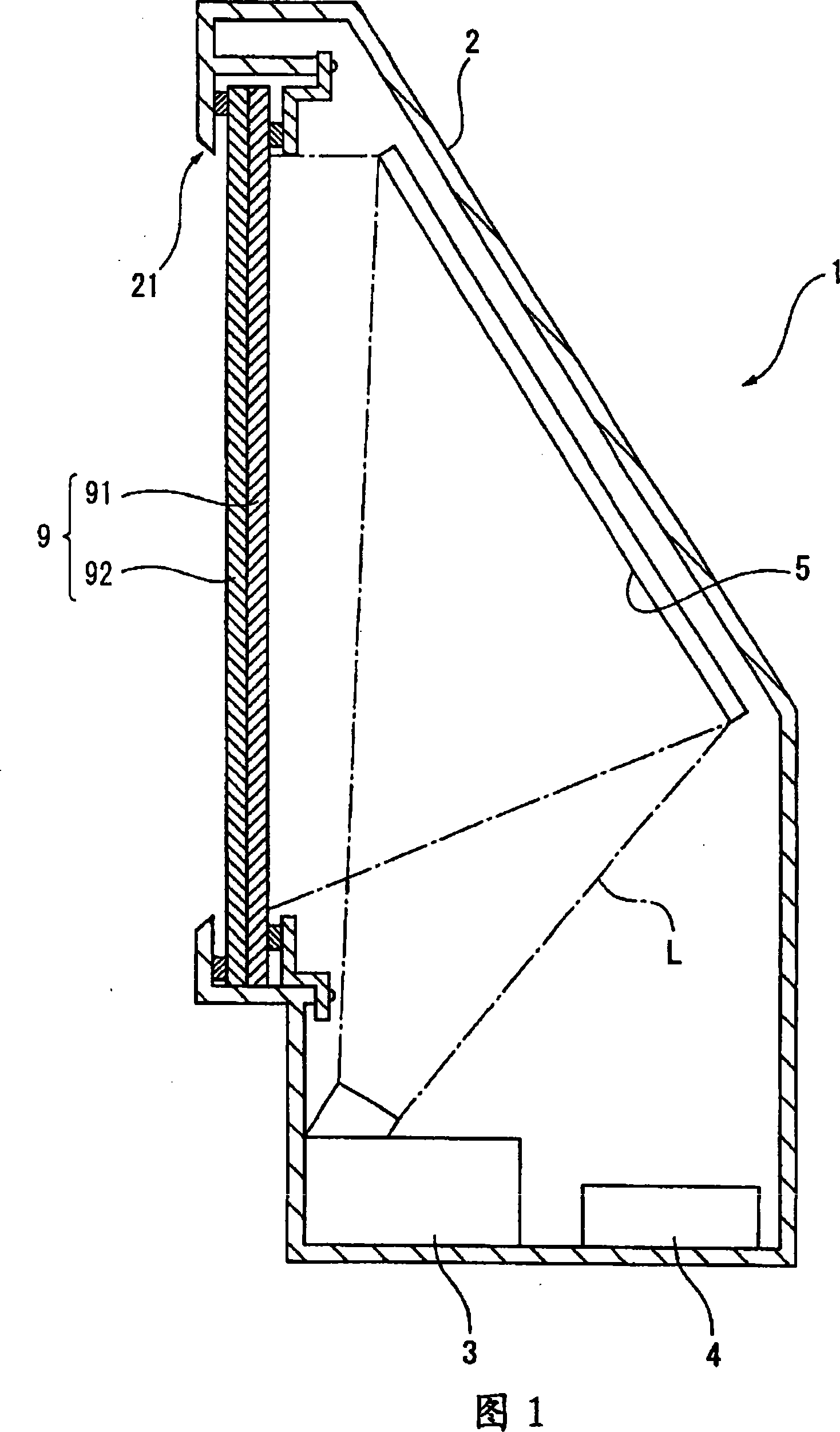
[0059] FIG. 1 is a side sectional view of a rear projection projector as a projector in the present invention. In FIG. 1 , a rear-projection projector 1 includes a casing 2 , a projection unit 3 , a control unit 4 , a mirror 5 , and a transmissive screen 9 .

[0060] The casing 2 is configured in a box shape with the rear side (the right side in FIG. 1 ) inclined, and accommodates and arranges the projection unit 3 , the control unit 4 and the reflection mirror 5 inside. In addition, the specific illustration is omitted, and inside the casing 2, in addition to the projection unit 3, the control unit 4, and the mirror 5, a power supply for supplying electric power to each component of the rear projection projector 1 is arranged. unit, a cooling unit for cooling the inside of the rear projection projector 1, a sound output unit for outputting sound, and the like.

[0061] In addition, on the front side (left side i...

no. 2 Embodiment approach

[0117] FIG. 7 is a schematic diagram showing a schematic configuration of a laser light source device in a second embodiment. The second embodiment is different from the configuration of the laser light source device 31 in the first embodiment, except that instead of the band-pass filter multilayer film 312B formed on the incident surface of the wavelength conversion element 312, a band-pass filter 412 is provided. Other than that, it has the same basic configuration as that of the aforementioned first embodiment. Therefore, the same reference numerals are attached to the same components as those in the first embodiment, and descriptions thereof are omitted or simplified. In addition, the same applies to the operation of each component, and its detailed description is also omitted or simplified.

[0118] (Structure of light source device)

[0119] In FIG. 7 , a laser light source device 41 includes a laser light source 311 for exciting laser light, a bandpass filter 412 , an...

no. 3 Embodiment approach

[0150] FIG. 9 is a schematic diagram showing a schematic configuration of a laser light source device in a third embodiment. The laser light source device 51 of the third embodiment differs from the laser light source device 41 in the second embodiment in configuration except that a multilayer mirror body 515 is arranged instead of the dielectric multilayer film 414C formed on the wavelength conversion element 414. Otherwise, it has the same basic configuration as that of the aforementioned first embodiment and second embodiment. Therefore, the same reference numerals are assigned to the same components as those in the first embodiment and the second embodiment, and descriptions thereof are omitted or simplified. In addition, the same applies to the operation of each component, and its detailed description is also omitted or simplified.

[0151] In FIG. 9, a laser light source device 51 includes a laser light source 311 for exciting laser light, a wavelength conversion elemen...


PUM


Abstract

The invention provides a laser source device which can well projects the laser with a low cost and a miniaturization and a projector with the laser source. The laser source device has: a laser source to actuate the laser with a predetermined wavelength and a laser conversion element to convert the laser wavelength projected from the laser source and project the converted laser. The wavelength conversion element has a band-pass filter multilayer film at the incident face, which makes the laser with an actuated wavelength projected from the laser source transmit selectively and a dielectric multilayer film at the emission face which makes the laser with the converted wavelength transmit and reflect the laser with the actuated wavelength. The laser whose wavelength is actuated in the band-pass filter multilayer is made into a narrow frequency. The laser with the narrow frequency is converted into a laser with a converted wavelength by a wavelength conversion element. The converted laser emits from the laser source device.

Description

technical field [0001] The present invention relates to a laser light source device that emits laser light, and a projector including the laser light source device. Background technique [0002] In recent years, in optoelectronic fields such as optical communication, optical application measurement, and optical display, laser light source devices employing wavelength conversion of excitation (oscillation) light of a semiconductor laser light source have been widely used. As such a laser light source device, there is known a second harmonic light generating device having a semiconductor laser light source with a mirror body structure formed on a single end surface and a non-reflective structure formed on its opposite surface, and Form a mirror body structure and form a non-reflective nonlinear optical member on its opposite surface; and form a resonator structure between the laser light source device and the mirror body structure of the nonlinear optical member, green light a...

Claims


Application Information

Patent Timeline
IPC IPC(8): H01S3/00G02F1/35
Inventor 小松朗矢野邦彦
Owner SEIKO EPSON CORP
Why Eureka
Try Eureka