Illuminating device for light steel frame

a technology of light steel frame and light fixture, which is applied in the direction of light fixture, fixed installation, lighting and heating apparatus, etc., can solve the problems of insufficient brightness and uneven illumination of conventional fluorescent tubes, insufficient brightness and unsatisfactory, and high price of light box b>1/b>, so as to improve the reflective efficiency, simplify the installation, and reinforce the effect of anti-dust

Inactive Publication Date: 2010-07-08
HSIEH CHEN HUANG
View PDF2 Cites 10 Cited by
  • Summary
  • Abstract
  • Description
  • Claims
  • Application Information

AI Technical Summary

Benefits of technology

[0006]The present invention is intended to solve the disadvantages of the conventional insert type and roof-mounted illuminating devices by providing a reasonable arrangement of the spatial illumination, simplification of installation, reinforcing the anti-dust effect, increasing the reflective efficiency, and s

Problems solved by technology

In a case that each light box 1a includes four T2/20 W fluorescent tubes each having a length of 1.2 meters, the consumed power is 80 W. In addition, the brightness and the illuminating efficiency of the conventional fluorescent tubes 3a are insufficient and unsatisfactory.
Furthermore, the light box 1a is bulky, expensive, and consumes considerable energy, such that two adjacent light boxes 1a are generally spaced by two or three sections.
The areas below the sections without light boxes 1a are darker, for they can only receive indirect, reflected illumination, leading to insufficient brightness and

Method used


Image

  • Illuminating device for light steel frame
  • Illuminating device for light steel frame
  • Illuminating device for light steel frame

Examples


Embodiment Construction

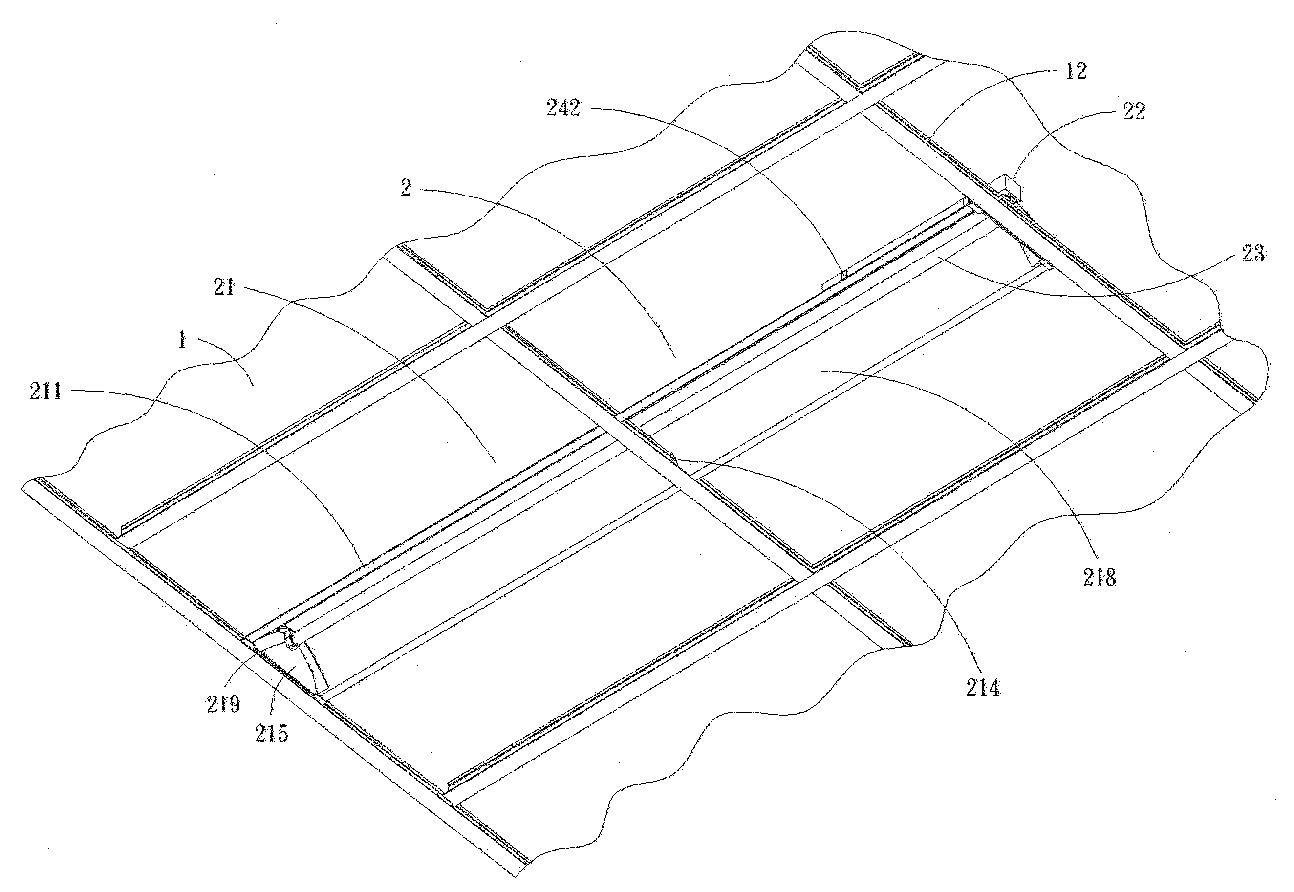
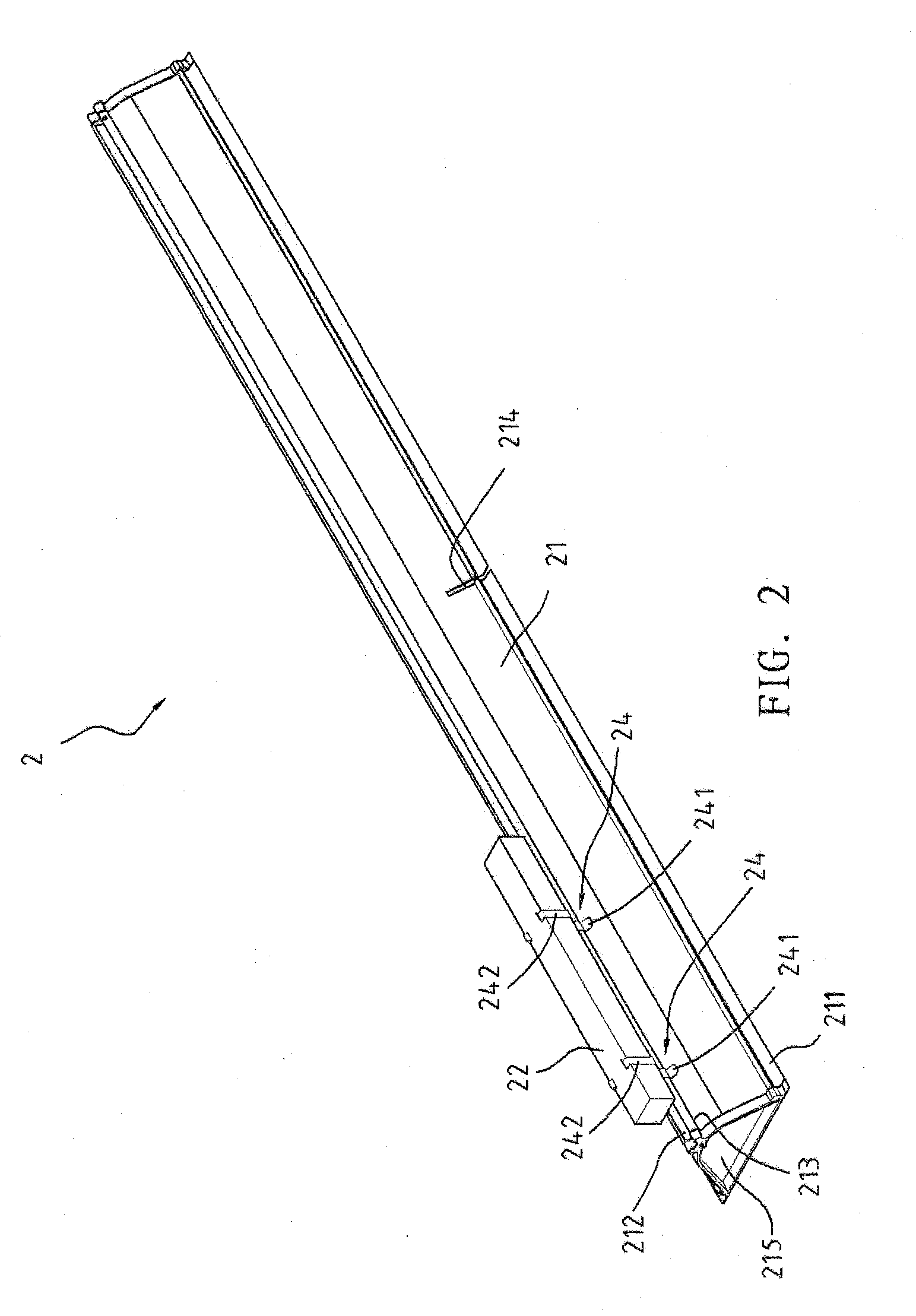
[0046]With reference to the drawings, an illuminating device 2 according to the preferred teachings of the present invention is generally mounted on a light steel frame 1 fixed to a ceiling. More particularly, the illuminating device 2 can be mounted across two or more sections of the light steel frame 1. The illuminating device 2 includes at least one elongated shade 21, an electronic stabilizer 22, a durable, energy-saving fluorescent tube 23, and first and second snap fasteners 24 and 25. An end cap 215 is mounted to each of two ends of the shade 21 and includes a light seat 219. The light seats 219 are aligned with each other. A bowl-shaped mirror reflector 216 is mounted in the shade 21 for concentrating and reflecting light beams and for avoiding accumulation of dust. The shade 21 is substantially bowl-shaped in cross section. The fluorescent tube 23 is mounted in the shade 21 and has an appropriate length (such as 2.4 m) corresponding to a length of a section of the light ste...


PUM


Abstract

An illuminating device is mounted on top of or below a light steel frame and includes at least one one-piece elongated shade in which a bowl-shaped mirror reflector is mounted. A fluorescent tube is mounted in the shade and longer than one of a plurality of sections of the light steel frame. A wing extends horizontally from each of two lateral sides of the shade. An extrusion ridge is formed on a top side of the shade. Two shield boards are mounted in each section of the light steel frame extended across by the shade. An edge of each shield board rests on one of the wings. First and second snap fasteners are selectively engaged with the extrusion ridge. The first snap fastener can fix an electronic stabilizer on the extrusion ridge. The second snap fastener can fix the illuminating device to a longitudinal beam of the light steel frame.

Description

BACKGROUND OF THE INVENTION[0001]The present invention relates to an illuminating device and, more particularly, to an illuminating device mounted on a light steel frame, providing anti-dust function, increasing brightness, saving electricity, allowing easy and rapid installation, and providing even brightness.[0002]Although fluorescent tubes have been significantly improved in lumen efficiency, service life, color rendering, and color temperature diversity, several general rules still apply. Namely, a thinner fluorescent tube is the brighter than a wider one; a straighter fluorescent tube is brighter than a curved one; and a longer fluorescent tube has higher efficiency and a longer service life. As an example, the brightness of a T8 / 40 W fluorescent tube is equal to that of three T8 / 20 W fluorescent tubes and has a service life two times of that of the T8 / 20 W fluorescent tubes. As another example, the brightness of a T5 / 28 W fluorescent tube is equal to that of a T8 / 40 W fluoresc...

Claims


Application Information

Patent Timeline
IPC IPC(8): F21V7/00
CPCF21S8/026F21S8/04F21Y2103/00F21V21/03F21V17/16
Inventor HSIEH, CHEN HUANG
Owner HSIEH CHEN HUANG
Why Eureka
Try Eureka