Image sensor and image capture device

a technology of image sensor and image capture device, which is applied in the field of image sensor, can solve the problems of reducing resolution and snr, difficult to reduce the size of such a device for rotating the polarizing plate, and difficult to reduce the size of such a device that changes the position of the polarizing plate, and achieves high resolution

Inactive Publication Date: 2012-07-05
PANASONIC CORP
View PDF0 Cites 16 Cited by
  • Summary
  • Abstract
  • Description
  • Claims
  • Application Information

AI Technical Summary

Benefits of technology

[0023]According to the present invention, as a shifter that shifts the polarizer array by a distance corresponding to the arrangement pitch of pixels parallel to the image capturing plane is used, there is no need to use a device of a big size ...

Problems solved by technology

On the other hand, if the conventional technique disclosed in Patent Document No. 2 were adopted, the problem of pixel shifting would be caused by the rotating polarizing plate, and therefore, the resolution and the SNR would decrease.
On top of that, it is difficult to reduce the size of su...

Method used


Image

  • Image sensor and image capture device
  • Image sensor and image capture device
  • Image sensor and image capture device

Examples


embodiment 1

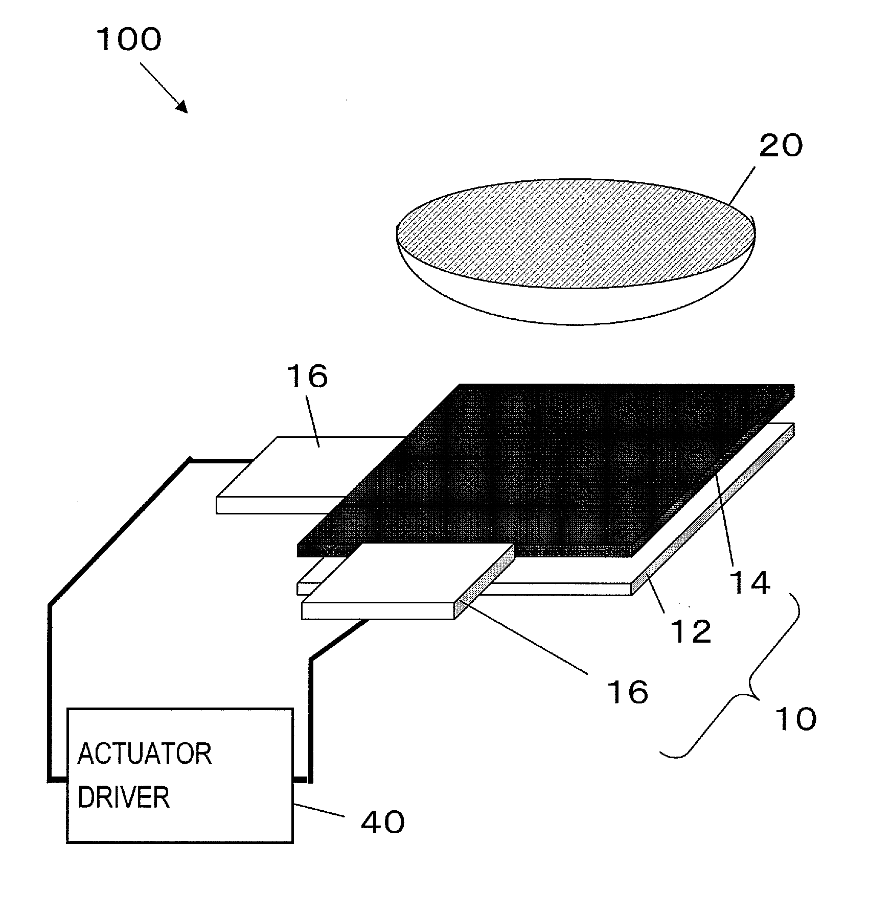
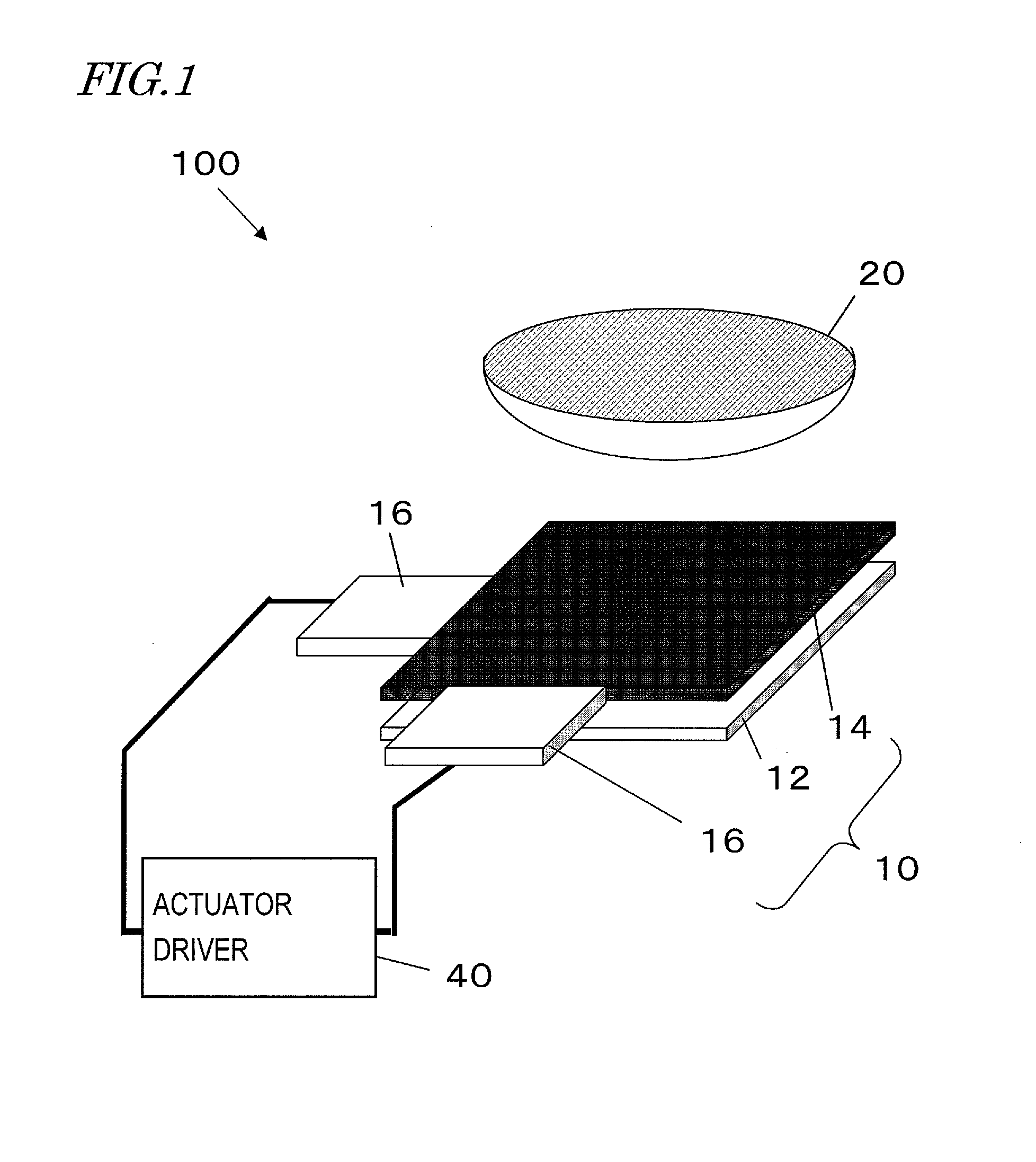
[0058]First of all, take a look at FIG. 1, which illustrates a general arrangement for an image capturing section of an image capture device as a first specific preferred embodiment of the present invention.

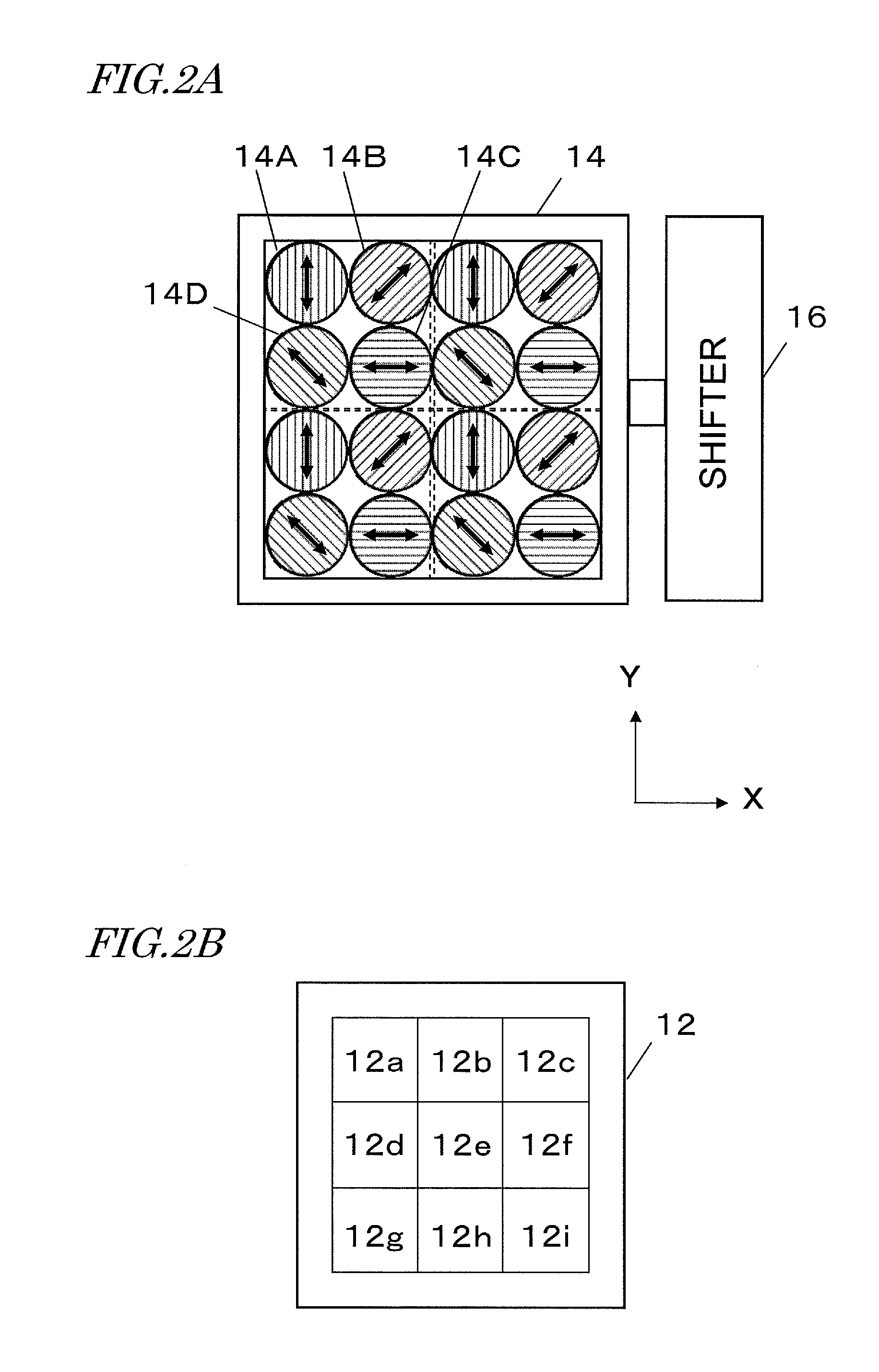
[0059]This image capturing section 100 includes an imager (i.e., image sensor) 10 and a shooting lens 20 for producing an image on the image capturing plane of the image sensor 10. Specifically, the image sensor 10 includes a photosensitive cell array 12 in which a plurality of photosensitive cells (i.e., photoelectric transducers) are arranged on the image capturing plane, a polarizer array (i.e., a polarization mosaic array plate) 14, and a shifter 16 for shifting the polarizer array 14 with respect to the photosensitive cell array 12 parallel to the image capturing plane.

[0060]The respective photosensitive cells correspond to pixels, and the photosensitive cell array 12 may also be called a “pixel array 12”. As will be described in detail later, a plurality of unit structures,...

embodiment 2

[0139]Hereinafter, a second preferred embodiment of an image sensor according to the present invention will be described.

[0140]The image sensor of this second preferred embodiment is different from the counterpart of the first preferred embodiment described above only in the arrangement pattern of polarizers in the polarizer array and how to shift the polarizer array. Thus, the following description of the second preferred embodiment will be focused on just these differences from the first preferred embodiment and their common configuration or operation will not be described all over again.

[0141]FIG. 19 is a top view illustrating the arrangement of the polarizer array of this preferred embodiment. In this polarizer array, four kinds of polarizers, which have mutually different polarization transmission axes, are arranged in stripes. FIG. 20A illustrates a part of the polarizer array shown in FIG. 19 and FIG. 20B illustrates an alternative arrangement pattern of polarizers. Both of t...


PUM


Abstract

In one embodiment of the present invention, an image capture device includes an image sensor 10 that includes: a photosensitive cell array 12 in which a plurality of photosensitive cells are arranged on an image capturing plane; a polarizer array 14 in which a plurality of unit structures, each including N polarizers (where N is an integer that is equal to or greater than two) that have mutually different polarization transmission axis directions, are arranged two-dimensionally and which is arranged so that light that has been transmitted through each polarizer is incident on its associated photosensitive cell; a circuit for reading a pixel signal from the photosensitive cell array 12; and a shifter 16 for shifting the polarizer array 14 with respect to the photosensitive cell array 12 parallel to the image capturing plane.

Description

[0001]This is a continuation of International Application No. PCT / JP2011 / 003933, with an international filing date of Jul. 8, 2011, which claims priority of Japanese Patent Application No. 2010-175542, filed on Aug. 4, 2010, the contents of which are hereby incorporated by reference.BACKGROUND OF THE INVENTION[0002]1. Field of the Invention[0003]The present invention relates to an image sensor that can obtain polarization information and to an image capture device including such an image sensor.[0004]2. Description of the Related Art[0005]Recently, polarization imaging has attracted a lot of attention as a technique for obtaining information that could not be gotten only with an intensity image. In order to carry out polarization imaging, either polarizers or a polarizing plate needs to be arranged in front of the image capturing plane of an image sensor. Japanese Patent Application Laid-Open Publication No. 2007-86720 (Hereinafter, Patent Document No. 1) discloses an image sensor i...

Claims


Application Information

Patent Timeline
IPC IPC(8): H04N5/335H01L27/146
CPCG02B26/00H04N5/349H04N5/2254G02B27/286H04N25/48
Inventor SINGH, BRAHM PAL
Owner PANASONIC CORP
Why Eureka
Try Eureka