Spectacle structure

a spectacle and structure technology, applied in the field of spectacle structure, can solve the problems of increasing the whole structural complexity, inconvenient use, and the manufacturing cost of eyeglasses, and achieve the effect of convenient disassembly

Active Publication Date: 2012-07-05
T LINK PPE
View PDF3 Cites 11 Cited by
  • Summary
  • Abstract
  • Description
  • Claims
  • Application Information

AI Technical Summary

Benefits of technology

[0007]With the above arrangements, the inner frame unit of the spectacle structure of the present invention can be firmly assembled to or conveniently disassembled from the rear side of the lens unit.

Problems solved by technology

However, either the adhesive structure or the clip-on structure or the magnetic structure is an external structure that not only increases the whole structural complexity and accordingly, the manufacturing cost of the eyeglasses, but also is inconvenient for use.

Method used


Image

  • Spectacle structure
  • Spectacle structure
  • Spectacle structure

Examples


first embodiment

[0025]In the variant of the present invention as shown in FIGS. 4 to 6, the posts 1133 may respectively have a slightly rearward bent top to look like a hook, so as to enable increased connecting strength between the inner frame unit 1 and the lens unit 2.

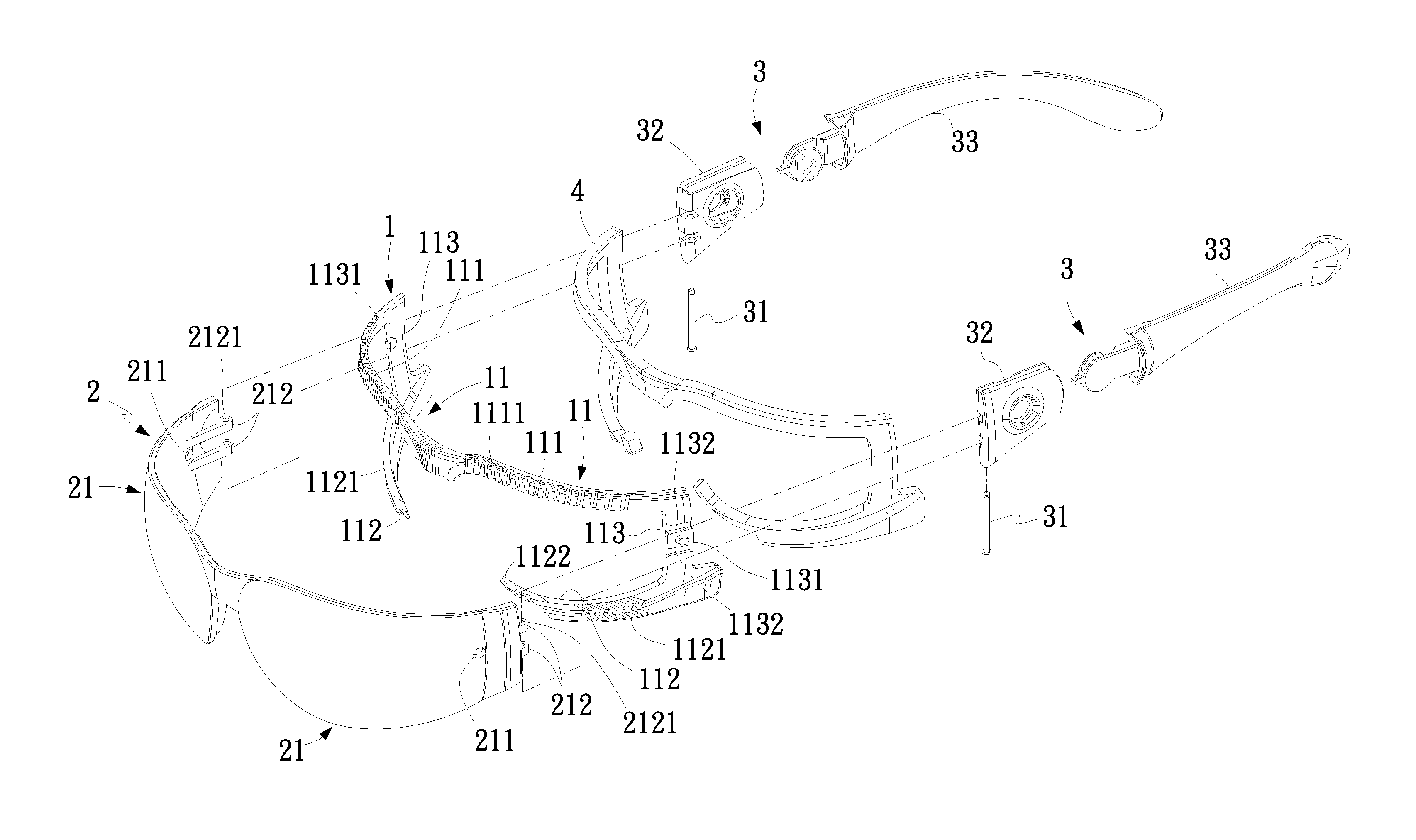
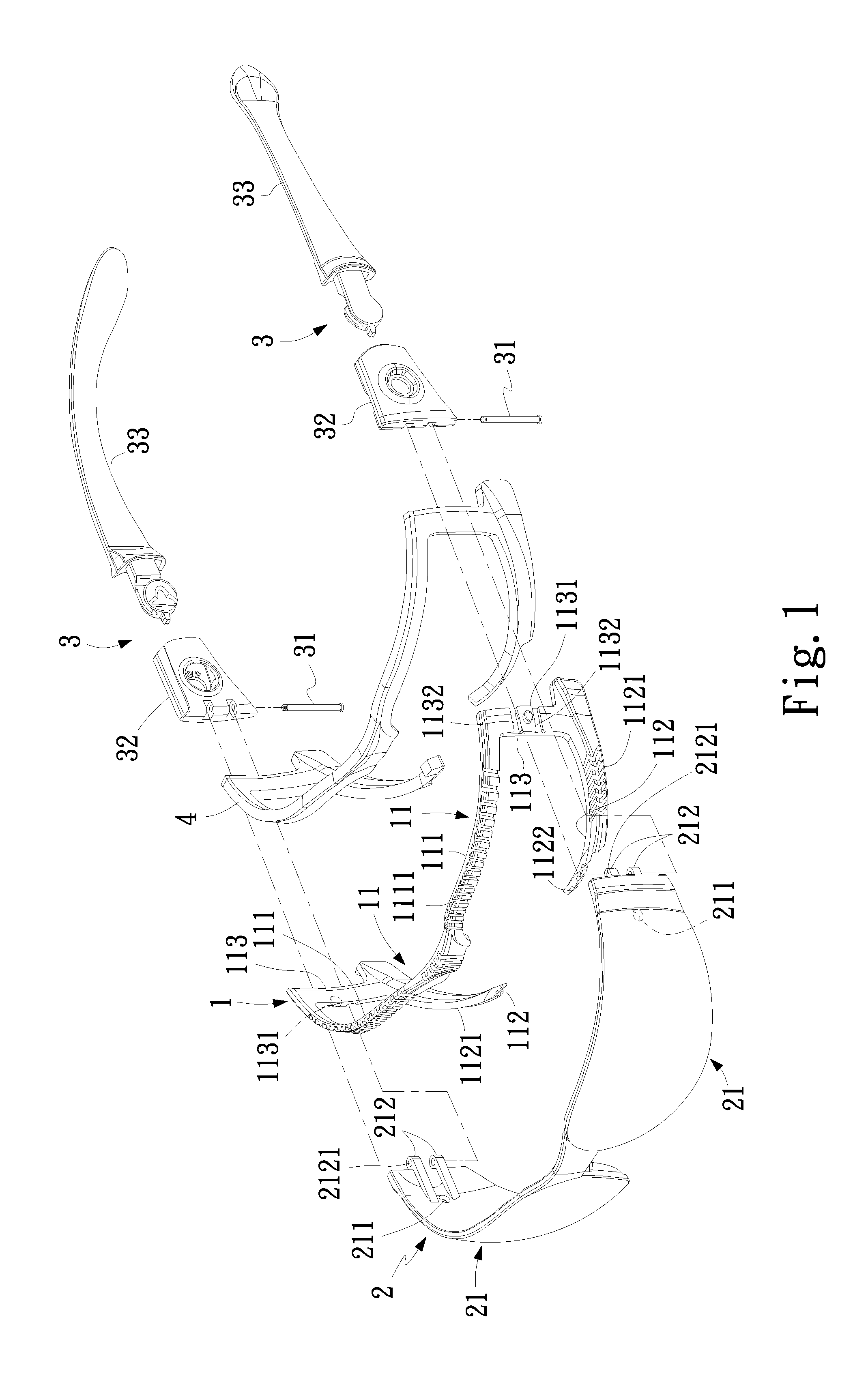
[0026]FIGS. 7 and 8 are exploded and assembled perspective views, respectively, of a spectacle structure according to a second embodiment of the present invention; and FIG. 9 is a fragmentary sectional view of the spectacle structure of FIG. 8. As shown, the spectacle structure according to the second embodiment of the present invention includes an inner frame unit 1, a lens unit 2, and a wear unit 3. The inner frame unit 1 includes two connected frame members 11. Each of the frame members 11 is a horizontal U-shaped member formed from three sequentially connected frame sections, namely, an upper frame section 111, a laterally outer frame section 113, and a lower frame section 112. The upper frame sections 111 are connected to each...

second embodiment

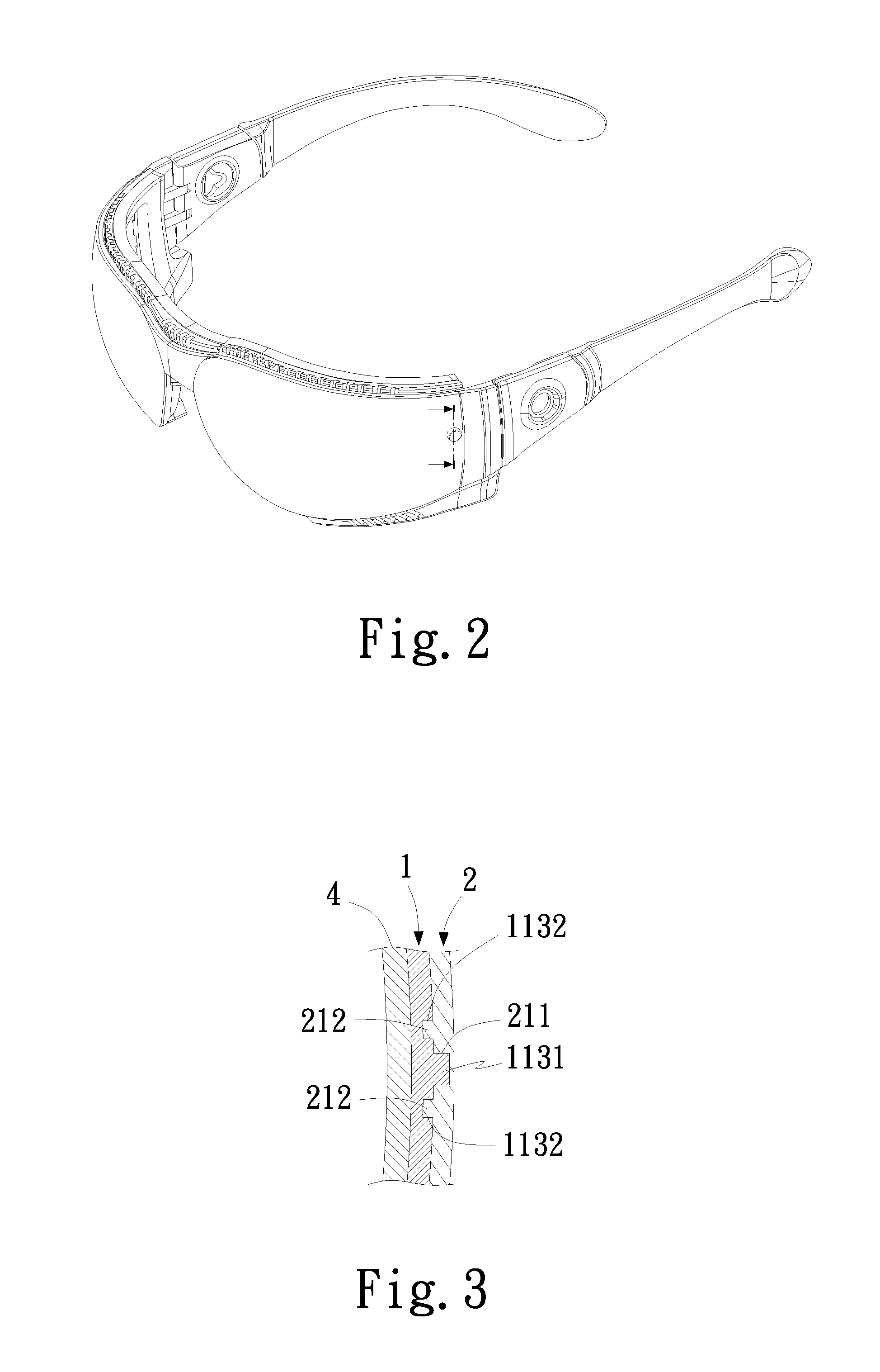
[0029]In the illustrated second embodiment, there are two parallelly spaced grooves 1132 provided on and extended across the laterally outer side of each of the two outer frame sections 113, and the recess 1134, 1135 is located between the two grooves 1132. Meanwhile, there are two parallelly spaced horizontal ribs 212 provided on the laterally inner side of each of the two lenses 21 facing toward the outer frame section 113. The two ribs 212 are separately received in the two grooves 1132 to enable enhanced guiding and restraining functions.

[0030]In both of the first and the second embodiment, the wear unit 3 is pivotally connected to between the two ribs 212 at each of two ends of the lens unit 2 to provide increased connecting strength between the wear unit 3 and the lens unit 2. Each of the ribs 212 is provided at a rear end with a pivot hole 2121. The wear unit 3 further includes two fixing elements for separately extending through one end of the two connecting elements 32 of t...


PUM


Abstract

A spectacle structure includes an inner frame unit having two connected horizontal U-shaped frame members respectively formed from an upper, a laterally outer and a lower frame section, the upper frame sections being connected to each other, each of the outer frame sections being provided with two horizontal grooves and a post or a recess or a through hole located between the two grooves, and each of the lower frame sections having a forward and inward extended support section; a lens unit having two connected lenses, each of which being provided with two horizontal ribs and a recess or a through hole or a post corresponding to the outer frame section, allowing the inner frame unit to be firmly assembled to and conveniently disassembled from a rear side of the lens unit; and a wear unit being pivotally connected to two opposite ends of the lens unit.

Description

FIELD OF THE INVENTION[0001]The present invention relates to a spectacle structure, and more particularly to a spectacle structure including an inner frame unit that can be firmly assembled to and conveniently disassembled from a rear side of a lens unit.BACKGROUND OF THE INVENTION[0002]A conventional spectacle structure, such as a pair of general optical eyeglasses, usually includes a lens frame, two lenses, and two temples. The lens frame includes two frame members for receiving the two lenses therein, such that the two lenses are separately fitted into the two frame members. The two temples are separately pivotally connected to two laterally outer frame sections of the two frame members. When it is desired to add a soft pad or a wind guard to a rear side of the lens frame for the pair of eyeglasses to be more comfortable for wearing or to prevent crosswind from directly blowing into a user's eyes, an adhesive structure, a clip-on structure, or a magnetic structure is usually used...

Claims


Application Information

Patent Timeline
Patent Type & Authority Applications(United States)
IPC IPC(8): G02C1/04G02C11/08
CPCG02C1/04G02C5/146G02C2200/08G02C2200/04G02C11/08
Inventor LIN, KUO-TSENG
Owner T LINK PPE
Why Eureka
Try Eureka