
Electronic device, assembling structure and assembling method

a technology of assembling structure and electronic device, which is applied in the direction of casing/cabinet/drawer details, casing/cabinet/drawer details, electrical equipment, etc., can solve the problems of electrical shock, scratching or scald, and achieve the effect of convenient disassembly and avoidance of unexpected disassembly

Active Publication Date: 2015-06-25
WISTRON CORP
View PDF3 Cites 0 Cited by
  • Summary
  • Abstract
  • Description
  • Claims
  • Application Information

AI Technical Summary

Benefits of technology

The invention is a cover for an electronic device that can be conveniently disassembled and prevented from being unexpectedly disassembled. This is achieved through a locking mechanism that allows the cover to be easily detached without unintentionally removing other components. This feature improves safety and prevents damage to the device.

Problems solved by technology

In order to improve maintenance convenience of the NAS equipment, the cover of some of the NAS equipment are designed to be easily disassembled without using any tool, though such design results in a fact that the cover is easy to be unexpectedly dissembled to cause danger, for example, a child may disassemble the cover when casually operating the equipment to cause electric shock, scratch or scald, etc.
Therefore, how to avoid the unexpected disassembling of the cover while maintaining the maintenance convenience of the equipment becomes an important issue in design of the equipment.

Method used


Image

  • Electronic device, assembling structure and assembling method
  • Electronic device, assembling structure and assembling method
  • Electronic device, assembling structure and assembling method

Examples


Embodiment Construction

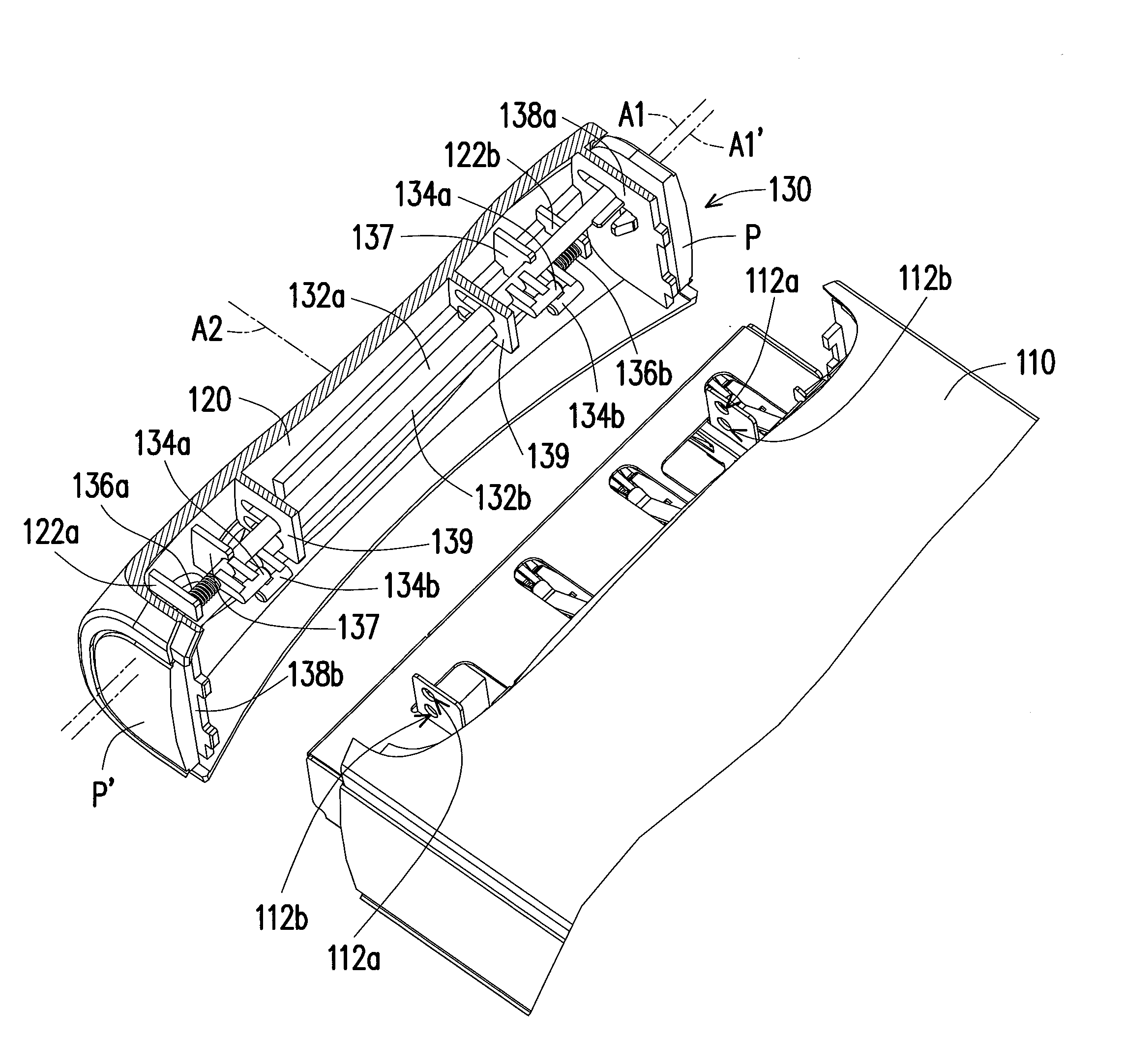
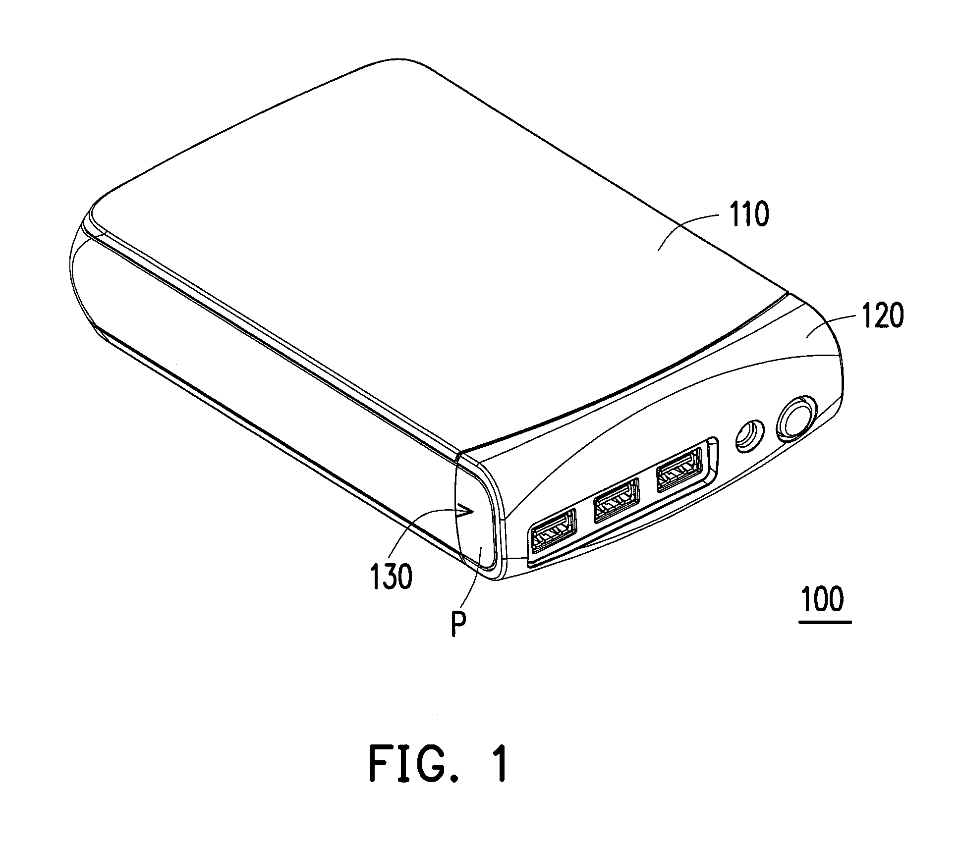
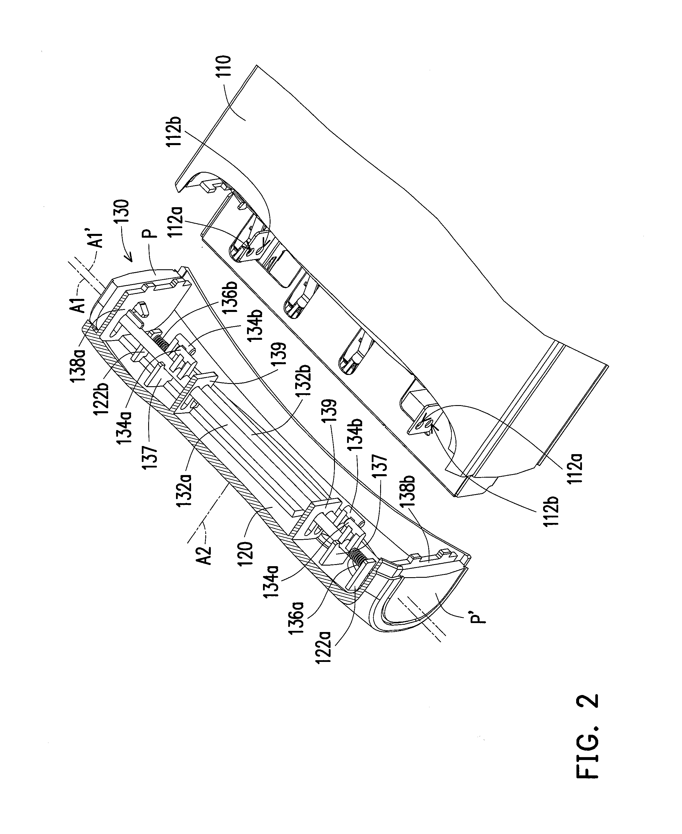
[0036]FIG. 1 is a three-dimensional view of an electronic device according to an embodiment of the invention. FIG. 2 is a partial exploded view of the electronic device of FIG. 1. FIG. 3 is a three-dimensional view of a cover and an assembling structure of the electronic device of FIG. 1. Referring to FIG. 1 to FIG. 3, the electronic device 100 of the present embodiment is, for example, networked attached storage (NAS) equipment and includes a main body 110, a cover 120 and an assembling structure 130. The main body 110 has at least one first positioning structure 112a (two first positioning structures 112a are illustrated) and at least one first positioning structure 112b (two first positioning structures 112b are illustrated), and the first positioning structures 112a and the first positioning structures 112b are, for example, positioning holes. The assembling structure 130 is disposed on the cover 120, and the main body 110 and the cover 120 can be assembled through the assemblin...


PUM

PropertyMeasurementUnit
elastic forceaaaaaaaaaa
outer diameteraaaaaaaaaa
thicknessaaaaaaaaaa

Abstract

An electronic device including a main body, a cover and an assembling structure is provided. The main body has two first positioning structures. The assembling structure includes two sliding components, two second positioning components and two elastic components. Each sliding component is slidably disposed on the cover and has a pressing portion. The second positioning structures are connected to the sliding components respectively and aligned to the first positioning components respectively. The elastic components are connected to the cover and connected to the sliding components respectively. Each second positioning component is positioned at the corresponding first positioning component by elastic force of the corresponding elastic component, so as to stop the cover separating from the main body. When the pressing portions receive forces at the same time to drive the second positioning structures to move away from the first positioning structures respectively, the cover is separated from the main body.

Description

CROSS-REFERENCE TO RELATED APPLICATION[0001]This application claims the priority benefit of China application serial no. 201310705899.2, filed on Dec. 19, 2013. The entirety of the above-mentioned patent application is hereby incorporated by reference herein and made a part of this specification.BACKGROUND[0002]1. Technical Field[0003]The invention relates to an electronic device, an assembling structure and an assembling method. Particularly, the invention relates to an electronic device having a detachable cover and an assembling structure and an assembling method thereof.[0004]2. Related Art[0005]Along with quick development of electronic technology, various electronic products have been widely used in people's daily life. Besides focusing on performance of the electronic products, consumers also have requirements on appearance, safety and maintenance convenience, etc. of the electronic products.[0006]Regarding networked attached storage (NAS) equipment, it generally has a cover ...

Claims


Application Information

Patent Timeline
Patent Type & Authority Applications(United States)
IPC IPC(8): H05K5/02H05K13/00
CPCH05K13/00H05K5/0217H05K5/03Y10T29/49826
Inventor MAO, ZHONG-HUI
Owner WISTRON CORP
Learn More