
Radiator fixing structure

a technology for fixing structures and radiators, applied in the field of radiators, can solve the problems of affecting reducing the execution speed or even the service life of components, and generating high heat during operation, and achieve the effect of convenient fixing and disassembly

Inactive Publication Date: 2020-08-27
EVGA CORPORATION
View PDF0 Cites 0 Cited by
  • Summary
  • Abstract
  • Description
  • Claims
  • Application Information

AI Technical Summary

Benefits of technology

The present invention aims to provide a radiator fixing structure that is easy to fix and disassemble. The radiator has convex portions on its bottom, and the base has guide, slide, and stop portions. The base is placed on the bottom of the radiator, and there is an inner ring portion with a positioning portion. The positioning portion is on one of the slide or guide portions and abuts against one of the stop portions. This allows the base to be easily disassembled from the bottom of the radiator and fixed in position.

Problems solved by technology

When using heating elements of internal devices of personal computers and notebook computers, such as motherboard, central processing unit, or integrated circuit components, they generate high heat during operation.
The faster the processing speed, the higher the relative thermal energy produced Therefore, the execution speed is reduced or even the service life of the components will be affected.
While screws are used for fixing and locking the support frame and the water-cooled radiator, but it is quite inconvenient to assemble and lock the support frame and the water-cooled radiator together, positions between the support frame and the water-cooled radiator need to be accurately aligned in order to lock properly, and also fastening the screws is time and labor consuming, and therefore causes inconvenience in fixing and disassembling.

Method used


Image

  • Radiator fixing structure
  • Radiator fixing structure
  • Radiator fixing structure

Examples


Embodiment Construction

[0023]The above object of the present invention, as well as its structural and functional features, will be described in accordance with the preferred embodiments of the drawings.

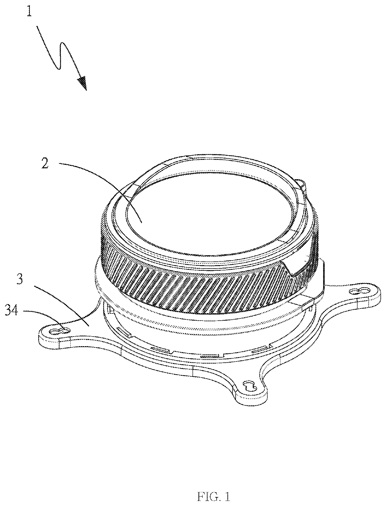
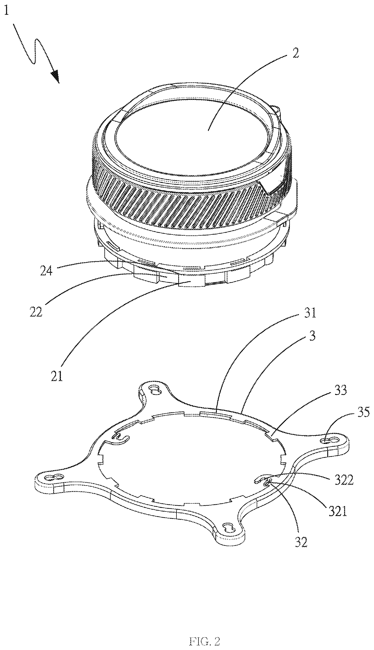
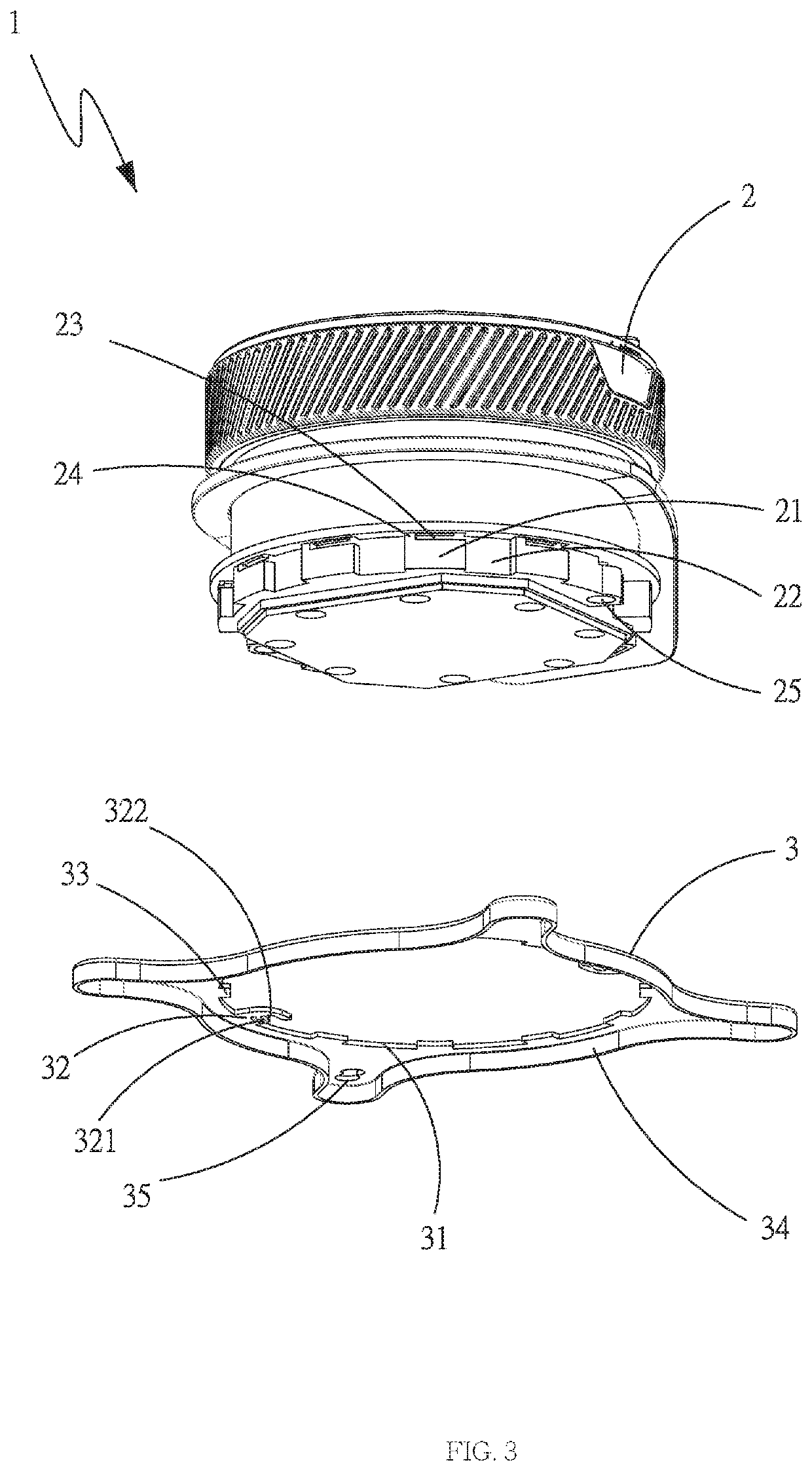
[0024]Please refer to FIG. 1 and FIG. 2 and FIG. 3, which are perspective assembled view, perspective exploded view and perspective exploded view from another angle of preferred embodiments of the present invention. It can be clearly seen from the figures that, a radiator fixing structure 1 mainly includes a radiator 2 and a base 3, wherein the radiator 2 is a water-cooled radiator in this embodiment.

[0025]Wherein at positions of a bottom the radiator 2 are formed with a plurality of convex portions 21, and the convex portions 21 are formed on a periphery of the radiator 2 and protrude outward from the radiator 2. At positions of the bottom the radiator 2 are formed with a plurality of guide portions 22 and a plurality of slide portions 23 and a plurality of stop portions 24. Each of the guide portions 22 i...


PUM


Abstract

The present invention provides a radiator fixing structure comprising a radiator and a base, the radiator has a plurality of convex portions and a plurality of guide portions, as well as a plurality of slide portions and a plurality of stop portions. The base is disposed on a bottom of the radiator, a center of the base has at least one positioning portion, and the positioning portion is disposed on one of the slide portions and abuts against one of the stop portions. The base is displaceable along the slide portion and one of the guide portions through the positioning portion, and is disassembled from the bottom of the radiator, thereby achieving the effect of being conveniently fixed and disassembled.

Description

BACKGROUND OF THE INVENTIONField of Invention[0001]The present invention relates to a radiator, and more particularly to a radiator fixing structure that can be conveniently fixed and disassembled.Related Art[0002]When using heating elements of internal devices of personal computers and notebook computers, such as motherboard, central processing unit, or integrated circuit components, they generate high heat during operation. The faster the processing speed, the higher the relative thermal energy produced Therefore, the execution speed is reduced or even the service life of the components will be affected. At this time, dissipating the thermal energy timely is a necessary solution, and radiator or radiator fin is usually disposed on the electronic component to increase the heat dissipation area and thereby enhancing the heat dissipation performance. However, due to the limited heat dissipation effect of the radiator and the radiator fin, the current conventional technology uses a wa...

Claims


Application Information

Patent Timeline
Patent Type & Authority Applications(United States)
IPC IPC(8): F28F9/007G06F1/20H05K7/20
CPCF28F9/007G06F1/20F28F2275/14H05K7/20263G06F2200/201H01L23/40H01L23/4006
Inventor HAN, TAI-SHENG
Owner EVGA CORPORATION
Learn More