Mounting structure of drive-shaft

a technology of mounting structure and drive shaft, which is applied in the direction of yielding couplings, control devices, vehicle components, etc., can solve the problems of difficult to meet the conditions of related art, difficult to maintain the constant velocity joint in the assembled state, and damage to parts of the driving system, so as to prevent the separation of the housing and facilitate the assembly and disassembly.

Active Publication Date: 2015-04-16
HYUNDAI MOTOR CO LTD
View PDF2 Cites 0 Cited by
  • Summary
  • Abstract
  • Description
  • Claims
  • Application Information

AI Technical Summary

Benefits of technology

[0016]Various aspects of the present invention provide for a mounting structure of a drive-shaft which can more conveniently assembled and disassembled and can prevent separation of a housing by bringing the housing in close contact with a companion flange, using the elastic force of a spring.

Problems solved by technology

That is, the rally cars frequently roll or fly at a high speed in accordance with the road or surrounding situations, so the parts of the driving system are likely to be damaged.
However, it was difficult to satisfy those conditions with the structures of the related art.
Accordingly, it was difficult to maintain the constant velocity joint in the assembled state (with the shaft and the housing combined) in the structure of the related art due to complicated assembly and separation.

Method used


Image

  • Mounting structure of drive-shaft
  • Mounting structure of drive-shaft
  • Mounting structure of drive-shaft

Examples


Embodiment Construction

[0042]Reference will now be made in detail to various embodiments of the present invention(s), examples of which are illustrated in the accompanying drawings and described below. While the invention(s) will be described in conjunction with exemplary embodiments, it will be understood that present description is not intended to limit the invention(s) to those exemplary embodiments. On the contrary, the invention(s) is / are intended to cover not only the exemplary embodiments, but also various alternatives, modifications, equivalents and other embodiments, which may be included within the spirit and scope of the invention as defined by the appended claims.

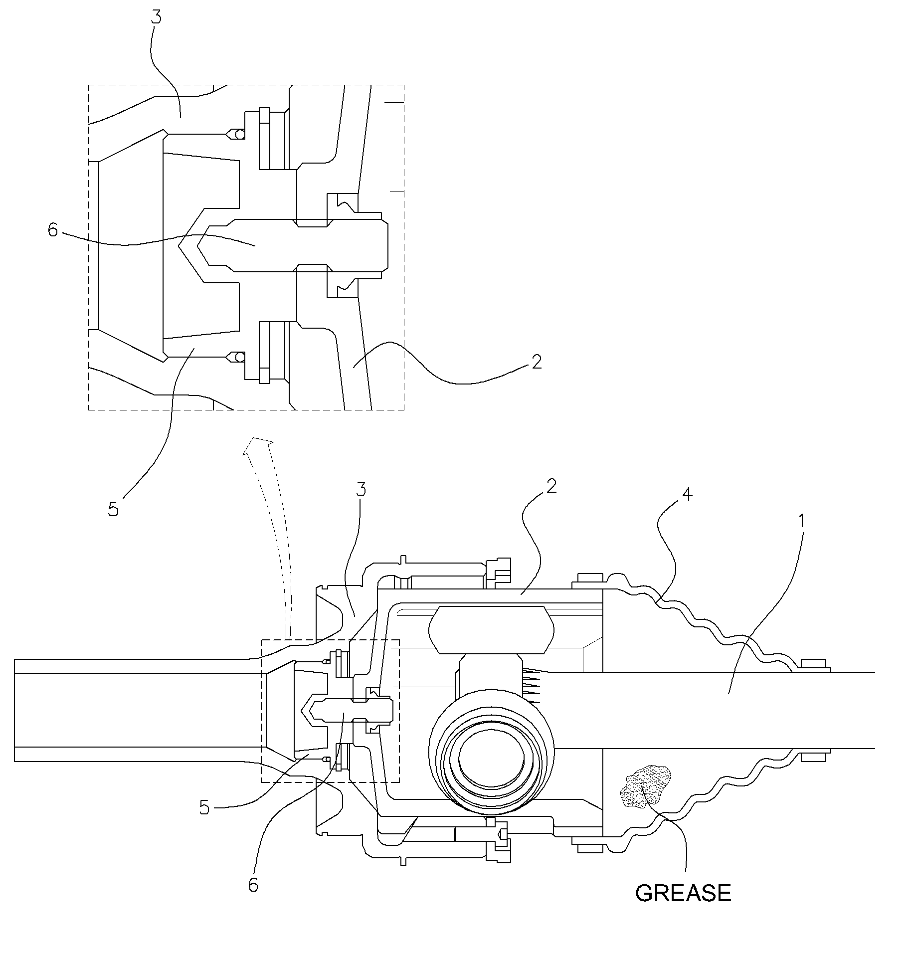
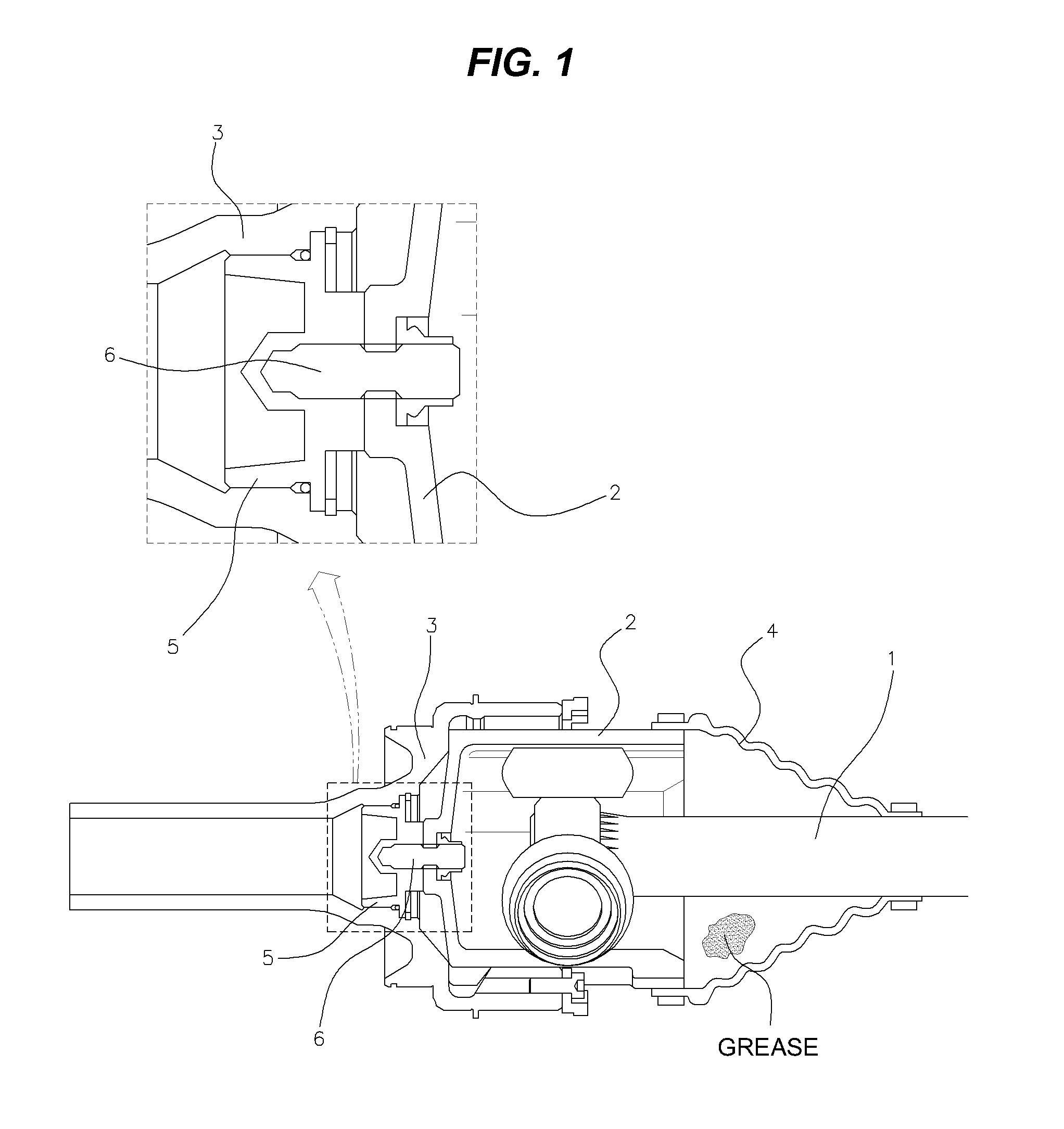
[0043]A drive-shaft according to the present invention has one side coupled to a transmission and the other side coupled to a wheel (in detail, a wheel-hub combined with the wheel), in which the sides are coupled, respectively, by a joint.

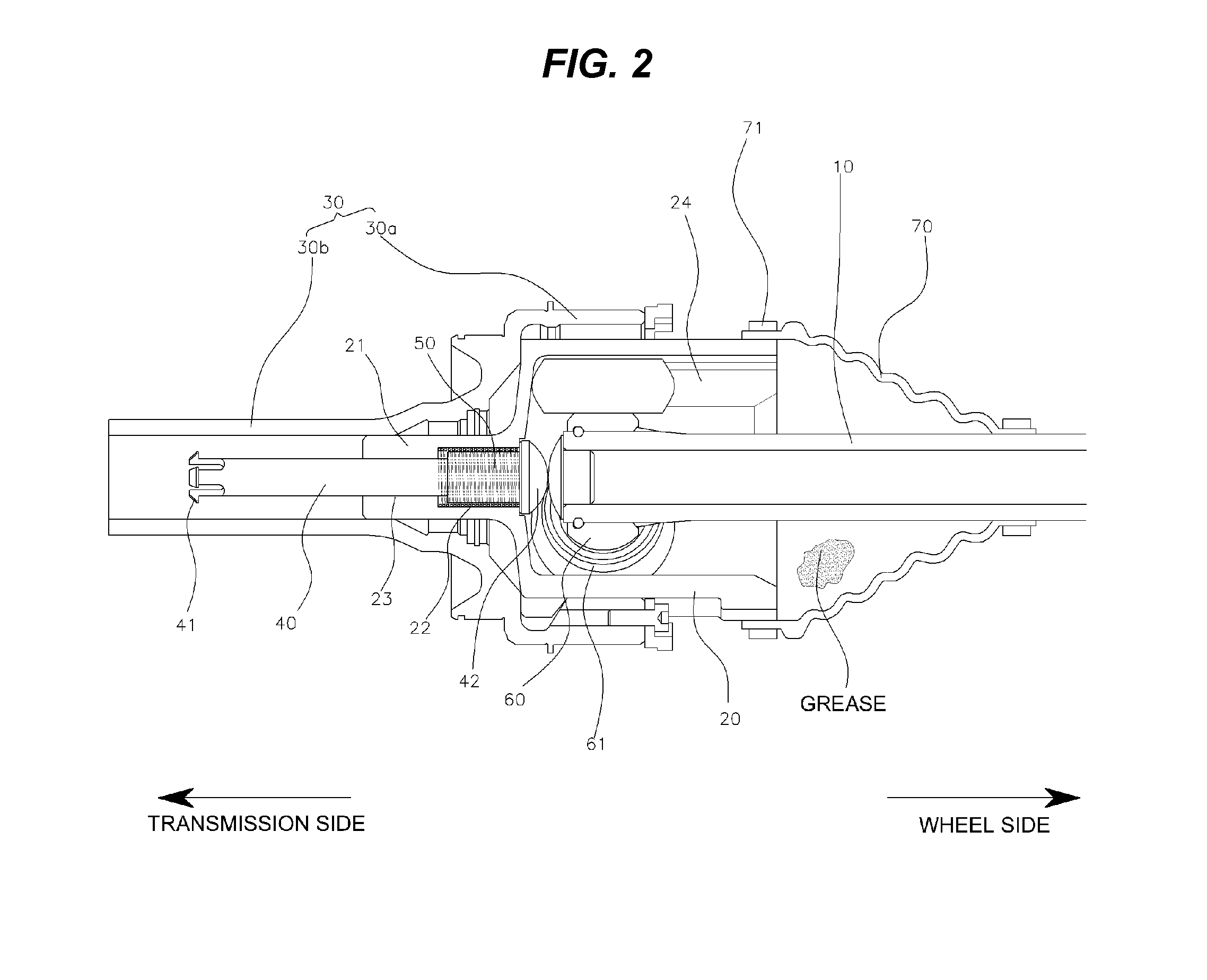
[0044]As shown in FIG. 2, a constant velocity joint at the side connected with the transmission i...


PUM


Abstract

A mounting structure of a drive-shaft includes: a shaft; a housing; a spring guide slidably disposed inside the housing having one end facing the shaft; and a spring with one end supported by a spring guide and the other end supported by the housing, in which a transmission has a companion flange with a cup-shaped coupling portion at an end, so when the housing enters the coupling portion, an elastic force of the spring biases the housing into the coupling portion. Since a fixing bolt is not used, it is possible to quickly assemble and disassemble the drive-shaft in maintenance.

Description

CROSS-REFERENCE TO RELATED APPLICATION[0001]The present application claims priority of Korean Patent Application Number 10-2013-0121338 filed Oct. 11, 2013, the entire contents of which application is incorporated herein for all purposes by this reference.BACKGROUND OF INVENTION[0002]1. Field of Invention[0003]The present invention relates to a mounting structure of a drive-shaft, and more particularly to a mounting structure of a drive-shaft that can prevent a constant velocity joint from separating by bring a housing of the constant velocity joint connected to a transmission in close contact with a companion flange in respect to changes in length and bending angle of a shaft due to behavior of a wheel, in a vehicle, such as a rally car, which requires rapid replacement of a drive-shaft to reduce maintenance time.[0004]2. Description of Related Art[0005]Rallies are held for rally cars modified from common vehicles and running not on exclusive racing roads, but specific sections. Th...

Claims


Application Information

Patent Timeline
Patent Type & Authority Applications(United States)
IPC IPC(8): F16D3/24F16D3/18F16D3/16
CPCF16D3/24F16D3/16F16D3/18F16D3/2055F16D2003/2232B60B35/00B60K17/24
Inventor YOO, SUNG-SUCHOI, WON-JUN
Owner HYUNDAI MOTOR CO LTD
Why Eureka
Try Eureka