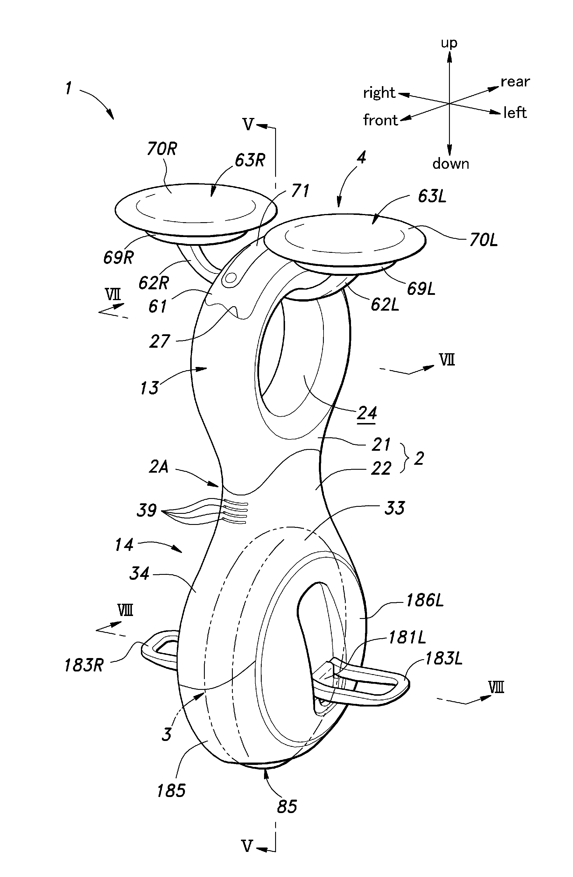
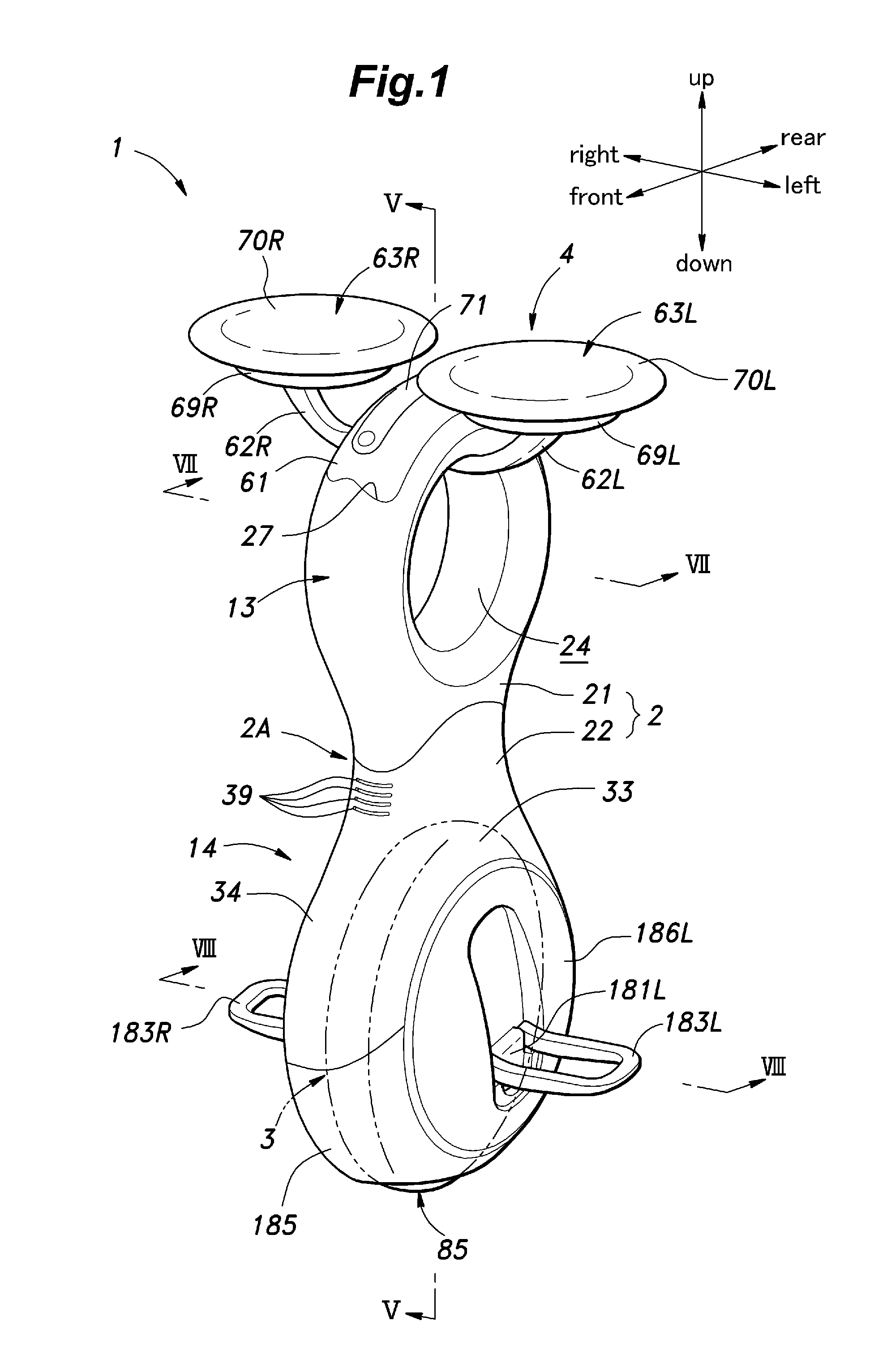
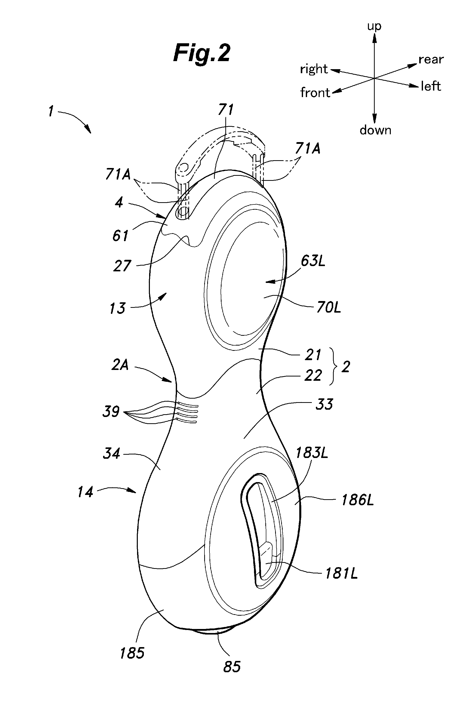
Inverted pendulum type vehicle

a pendulum type, inverted technology, applied in the direction of foldable cycles, cycle equipment, cycles, etc., can solve the problems of inability difficult to achieve turning maneuvers, and inability to steer, etc., to achieve stable manner and apply torque

Inactive Publication Date: 2012-07-12
HONDA MOTOR CO LTD
View PDF9 Cites 18 Cited by
  • Summary
  • Abstract
  • Description
  • Claims
  • Application Information

AI Technical Summary

Benefits of technology

[0010]A rigid body has three principal axes of inertia. The rotation of a rigid body around one of the principal axes of inertia does not couple with the rotation of the rigid body around the other principal axes of inertia, and can therefore be performed in a stable manner. In particular, it is possible to apply a torque to a vehicle by dynamically displacing an object supported by the vehicle. If the associated principal axis of inertia is tilted rearward, the principal axis of inertia crosses the ground surface at a point located ahead of the ground contact point of the main wheel of the vehicle. If the object supported by the vehicle shifts the gravitational center thereof in either lateral direction, and causes the vehicle to tilt in the corresponding direction, the main wheel is caused to rotate around the principal axis of inertia so that the vehicle is steered in effect, and can be turned in the corresponding direction.
[0011]This can be applied to a vehicle provided with a pair of wheels on either side, but can be particularly favorably applied to a vehicle that comprises a plurality of driven rollers provided on the main wheel so as to be rotatively driven around a circumferential axial line of the main wheel, and a lateral motion control unit configured to maintain the vehicle in an upright posture by controlling a rotational drive force applied to each driven roller according to a condition of the vehicle.
[0012]If the principal axis of inertia consists of a minimum principal axis of inertia, the rotation around this axial line can be achieved particularly easily so that the vehicle can turn in a favorable manner by taking advantage of such a rotation. When the vehicle further comprises a battery for powering the drive unit, the battery being positioned such that a gravitational center of the battery is located above and behind a gravitational center of the vehicle and / or when the drive unit comprises an electric motor, the electric motor being positioned such that a gravitational center of the electric motor is located below and ahead of a gravitational center of the vehicle, the substantially vertically directed principal axis of inertia may consist of a minimum axis of inertia that involves a minimum moment of inertia.

Problems solved by technology

However, as the vehicle travels on a single wheel, a steering action is not possible.
The vehicle may be able to travel in oblique directions, but involves some difficultly in achieving a turning maneuver that involves a yaw rate.
However, when this is actually attempted by the inventors, it was discovered that the turning maneuver cannot be achieved without experiencing some difficulty.
This allows a turning movement to be achieved in a favorable manner, but complicates the structure of the vehicle because of the need for the additional ground contact member and a control arrangement for controlling the action of the ground contact member.

Method used


Image

  • Inverted pendulum type vehicle
  • Inverted pendulum type vehicle
  • Inverted pendulum type vehicle

Examples


first embodiment

[0117]A rider sits on the saddle 152 with his back facing the frame 150. Similarly as in the first embodiment, as the rider shifts his weight laterally or in the fore and direction, the vehicle travels in the corresponding direction at a corresponding speed. In this case also, the vehicle can perform translational movement at will, but some effort could be required when a turning movement is attempted. Therefore, the minimum principal axis of inertia of the vehicle extending along the axial direction of the frame is tilted rearward with respect to the plumb vertical line. Therefore, as the rider laterally shifts his weight as an attempt to tilt the vehicle in the corresponding direction, a rotational movement around the minimum principal axis of inertia of the vehicle is created, and the vehicle can be turned in the desired direction.

third embodiment

[0118]FIG. 18 shows the inverted pendulum type vehicle according to the present invention. In FIG. 18, the parts corresponding to those of the previous embodiments are denoted with like numerals without repeating the description of such parts. This inverted pendulum type vehicle comprises a box-shaped frame 191 having an open bottom and a drive unit 3 similar to those of the previous embodiments fixedly secured inside the frame 191 and provided with a main wheel 85 engaging the ground surface G. The drive unit 3 is substantially covered by the frame 191 except for the lower part of the main wheel 85 which is exposed at a bottom opening 193 of the frame 191.

[0119]The drive unit 3 is provided with a pair of electric motors 195 which are attached to the free end of a motor arm 196 that extends forwards from the front face of the frame 191, instead of being coaxially disposed with the main wheel 85, and power is transmitted from the electric motors 195 to the drive unit 3 via a pair of ...


PUM


Abstract

The present invention provides an inverted pendulum type vehicle which can perform a turning movement with ease without requiring any additional device even though the vehicle is configured to travel on a single drive wheel. A substantially vertical principal axis of inertia of the vehicle is tilted rearward with respect to a plumb vertical line. As result, when a rider shift his gravitational center in either lateral direction and tilts the vehicle in the corresponding direction, the main wheel is caused to turn around the principal axis of inertia so that the main wheel is steering in effect, and the vehicle can be turned in a desired direction.

Description

TECHNICAL FIELD[0001]The present invention relates to an inverted pendulum type vehicle which is configured to travel while maintaining an upright posture, and in particular to an inverted pendulum type vehicle which travels on a single wheel consisting of a drive wheel and can change the traveling direction.BACKGROUND OF THE INVENTION[0002]Known is an inverted pendulum type vehicle that comprises a pair of drive assemblies individually actuated by electric motors and a main wheel held between the drive assemblies and frictionally driven by the drive assemblies. See Patent document 1, for instance. The main wheel disclosed in Patent document 1 comprises a ring-shaped annular member and a plurality of driven rollers arranged along the circumference of the annular member so as to be rotatable around axial line parallel to the respective tangential lines of the annular member, and the driven rollers are driven by the drive assemblies that engage the driven rollers. When the driven roll...

Claims


Application Information

Patent Timeline
Patent Type & Authority Applications(United States)
IPC IPC(8): B60K1/00B62D61/00
CPCB62J1/005B62J25/00B62K15/00B62K3/007B62K1/00B62K11/007B62J25/04
Inventor GOMI, HIROSHITAKENAKA, TORU
Owner HONDA MOTOR CO LTD
Why Eureka
Try Eureka