Printing device and printing method

a printing device and printing method technology, applied in the direction of printing, measuring devices, instruments, etc., can solve the problems of unstable back tension of the intermediate transfer film, inability to provide stable back tension for the ink ribbon, and inability to achieve stable back tension, so as to improve the printing quality

Active Publication Date: 2012-07-12
TOPPAN PRINTING CO LTD +1
View PDF5 Cites 17 Cited by
  • Summary
  • Abstract
  • Description
  • Claims
  • Application Information

AI Technical Summary

Benefits of technology

[0009]While taking the above described problems into account, one objective of the present invention is to provide a printing device that produces high quality printing and a printing method therefor.
[0016]According to the present invention, when or after the intermediate transfer medium and the ink ribbon that are conveyed have reached the printing start position, conveying of them is still continued (without being halted) and selective heating of the heating elements included in the thermal head is performed for image forming on the intermediate transfer medium. Therefore, the printing start position of the intermediate transfer medium will not be shifted due to a change in the trajectory that is caused by pressing the thermal head and the platen against each other. Further, since conveying of the intermediate transfer medium and the ink ribbon is not halted until image forming has been completed, the conveyance speed for the intermediate transfer conveyance and the ink ribbon is stabilized, a slackness does not occur in the intermediate transfer medium and the ink ribbon, and a stable back tension is obtained, so that an improvement in the printing quality can effectively be obtained.

Problems solved by technology

Therefore, when the intermediate transfer film and the ink ribbon have been set in position, and when conveying of the intermediate transfer film and the ink ribbon is temporarily halted and printing is started thereafter, a problem has arisen in that there is a difference in the printing density between immediately after the conveying of the intermediate transfer film and the ink ribbon is restarted and after the rotation of the motor has been stabilized.
Furthermore, in a case wherein printing (image forming relative to the intermediate transfer film) is to be performed after the intermediate transfer film and the ink ribbon have been aligned with each other, a problem encountered is that since when the conveying of the intermediate transfer film and the ink ribbon is halted (positioning having been completed) a slackness develops in the ink ribbon, and the back tension that is to be provided for the intermediate transfer film and the ink ribbon is not stable.

Method used


Image

  • Printing device and printing method
  • Printing device and printing method
  • Printing device and printing method

Examples


Embodiment Construction

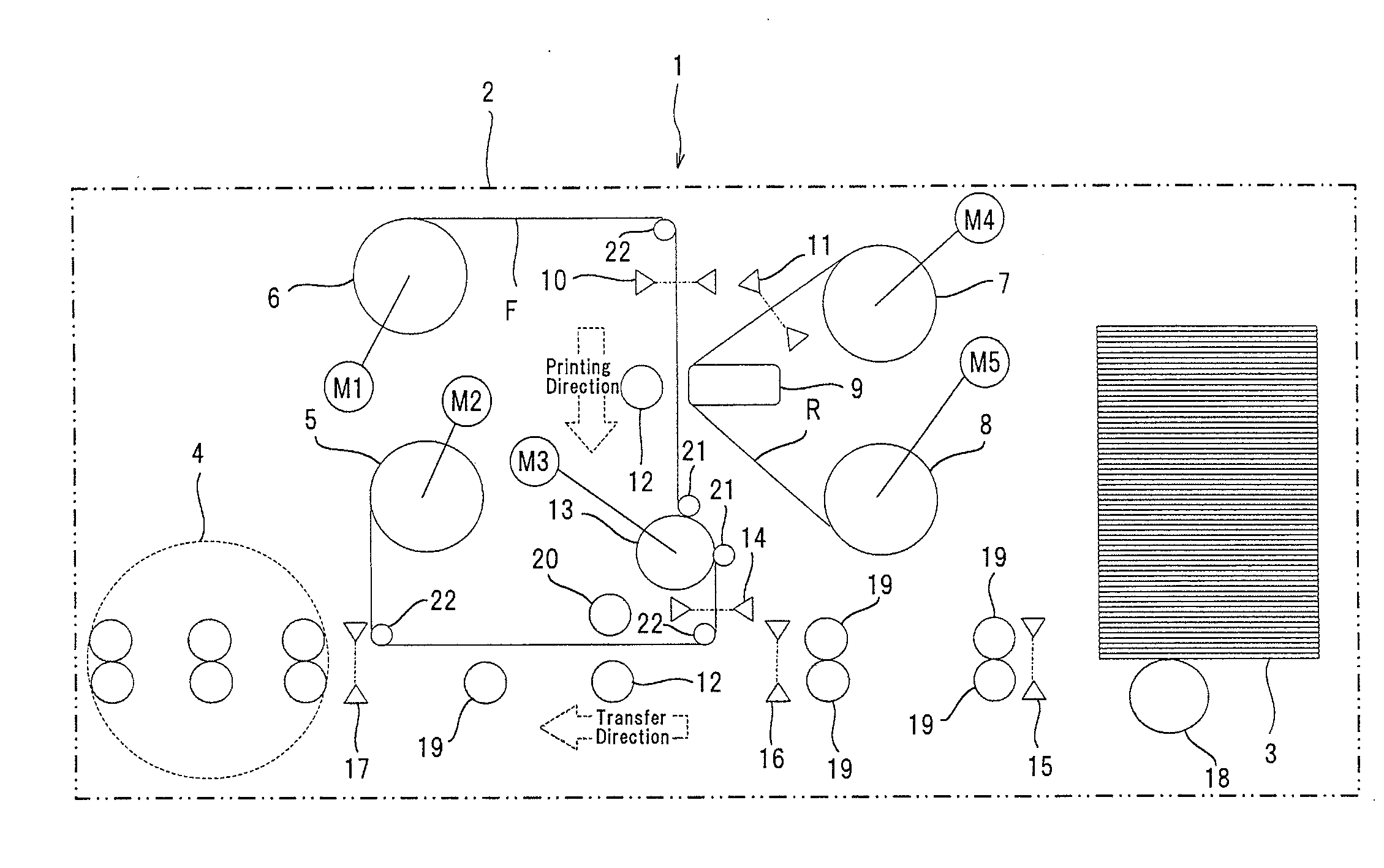
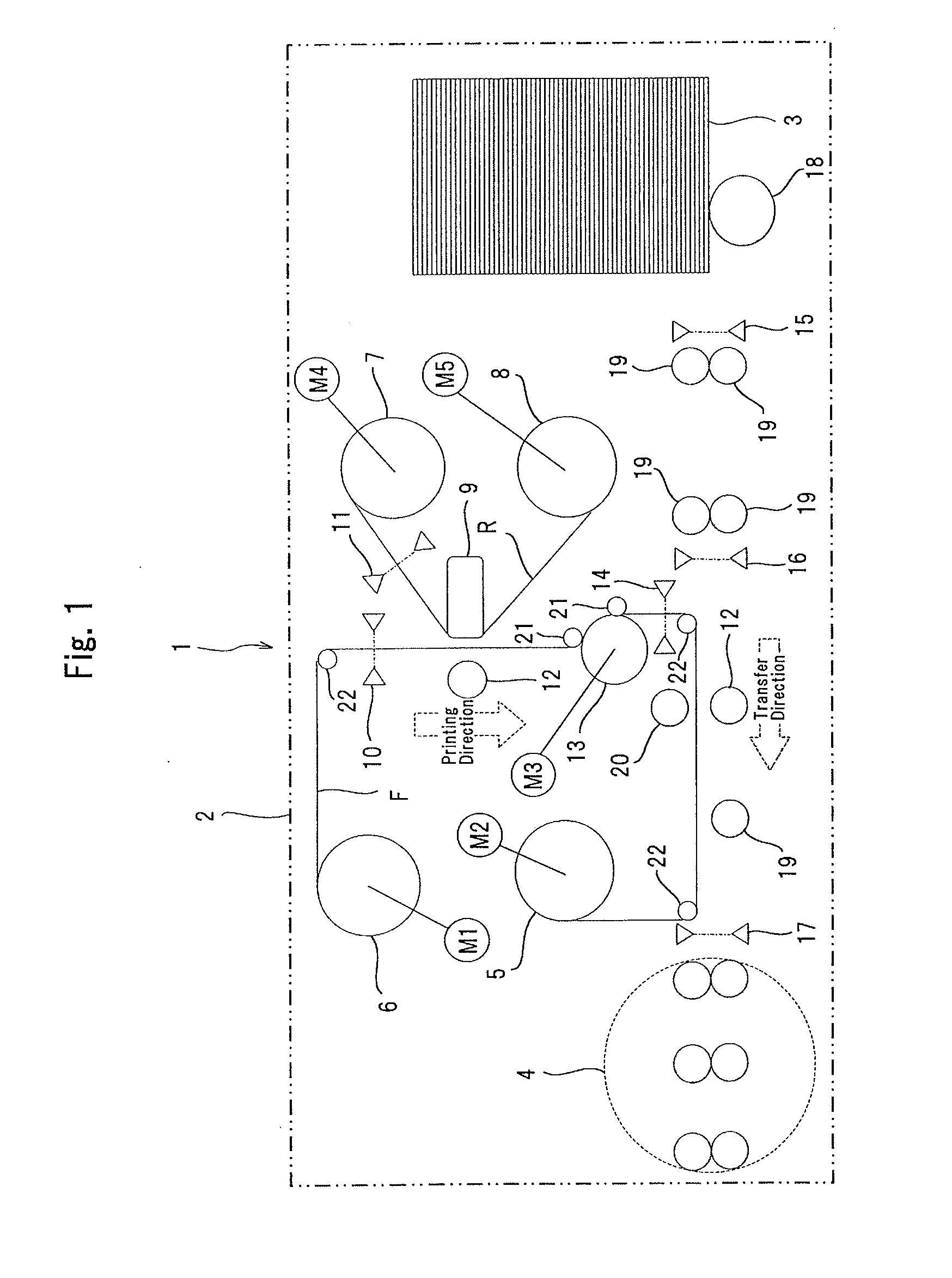
[0034]A description will now be given for embodiments wherein the present invention is applied for a printing device that performs printing by transferring images to a card type recording medium (hereinafter referred to as a card).

Configuration

[0035]As illustrated in FIG. 1, for a printing device 1 of one embodiment of this invention, a cabinet 2 employed as a housing includes: a card supply section 3, which is a card supply source; a card conveyance section that conveys a card, supplied from the card supply section 3, along a substantially horizontal, linear card conveyance path; a card rotation section 4, which is located at the end of the card conveyance section opposite the card supply section 3, and while nipping (sandwiching) a card, rotates the card at a predetermined angle; an image forming section that serves as a printing section including a thermal head 9 and a platen roller 12; an intermediate transfer film conveyance section that conveys an intermediate transfer film F ...


PUM


Abstract

The present invention provides a printing device which provides high printing quality. The printing device includes: an image forming section which has a thermal head 9 and a platen roller 12; a media conveyance section for conveying an intermediate transfer film F; a ribbon conveyance section for conveying an ink ribbon R; a sensor 10 for detecting a first mark formed on the film F; and a control section for controlling the image forming section, the media conveyance section, and the ribbon conveyance section in accordance with output information from the sensor 10. The control section presses the head 9 into contact with the roller 12 when the first mark is not detected, which is when the first mark is further upstream than the position of the sensor 10, while the film F and the ribbon R are being conveyed, and selectively heats a heating element formed in the head 9 when the film F is positioned in the printing start position, which is a state in which the first mark is detected when the first mark is further downstream than the position of the sensor 10.

Description

FIELD OF THE INVENTION[0001]The present invention relates to a printing device and a printing method, and relates particularly to a printing device and a printing method for pressing a thermal head against a platen, through an ink ribbon, and forming an image on a film-shaped intermediate transfer medium, and for transferring the thus obtained image to a printing medium.DESCRIPTION OF THE RELATED ART[0002]Conventionally, for the production of a print medium, such as a credit card, a cash card, a license card or an ID card, a printing device is employed whereby a thermal head is pressed against a platen roller, via an ink ribbon, to form an image on a film-shaped intermediate transfer medium (an intermediate transfer film), and the thus obtained image is transferred to a print medium.[0003]This printing device generally includes: an image forming section (a printing section), which has a thermal head and a platen roller, and is movable between a retracted position, where the thermal ...

Claims


Application Information

Patent Timeline
Patent Type & Authority Applications(United States)
IPC IPC(8): B41J2/325
CPCB41J2/0057B41J17/02B41J2/325
Inventor MOCHIZUKI, HIROSHIAIHARA, YUICHIKUBOTA, TSUYOSHI
Owner TOPPAN PRINTING CO LTD
Why Eureka
Try Eureka