
Core of Light Water Reactor and Fuel Assembly

a light water reactor and fuel assembly technology, applied in the direction of nuclear reactors, nuclear elements, greenhouse gas reduction, etc., can solve the problems of severe restrictions on tru recycling, and achieve the effect of sacrificing the economic efficiency of a light water reactor and increasing the safety margin

Active Publication Date: 2012-07-12
HITACHI-GE NUCLEAR ENERGY LTD
View PDF1 Cites 0 Cited by
  • Summary
  • Abstract
  • Description
  • Claims
  • Application Information

AI Technical Summary

Benefits of technology

[0009]A light water reactor for recycling TRU was achieved in R. TAKEDA et al., Proc. of International Conference on Evaluation of Emerging Nuclear Fuel Cycle Systems. GLOBAL '95 Versailles, France, September, 1995, P. 938; such that a recycle reactor effectively uses a seed fuel, in which the amount of TRU is maintained constant, with a sufficient safety margin to meet design standards for abnormal transience and accidents; and that the recycle reactor can stabilize supply of energy for a long period of time by burning all depleted uranium, and by making all the TRU undergo fission, the recycle reactor prevents the TRU from becoming a long-life radioactive waste at the end of the nuclear fission reactor's purpose when the TRU has become no longer necessary. On the other hand, there has recently been a movement to tighten up the attitude toward safety; consequently, a core having a high safety potential is expected, having a sufficient safety margin for responding to an accident outside the design standards (Anticipated Transient Without Scram, or ATWS) such as, for example, a compound event where the core flow rate suddenly drops for some reason and all control rods cannot be inserted into the core.
[0010]An object of the present invention is to provide a core of a light water reactor and a fuel assembly which can further increases a safety margin without sacrificing an economic efficiency of the light water reactor.
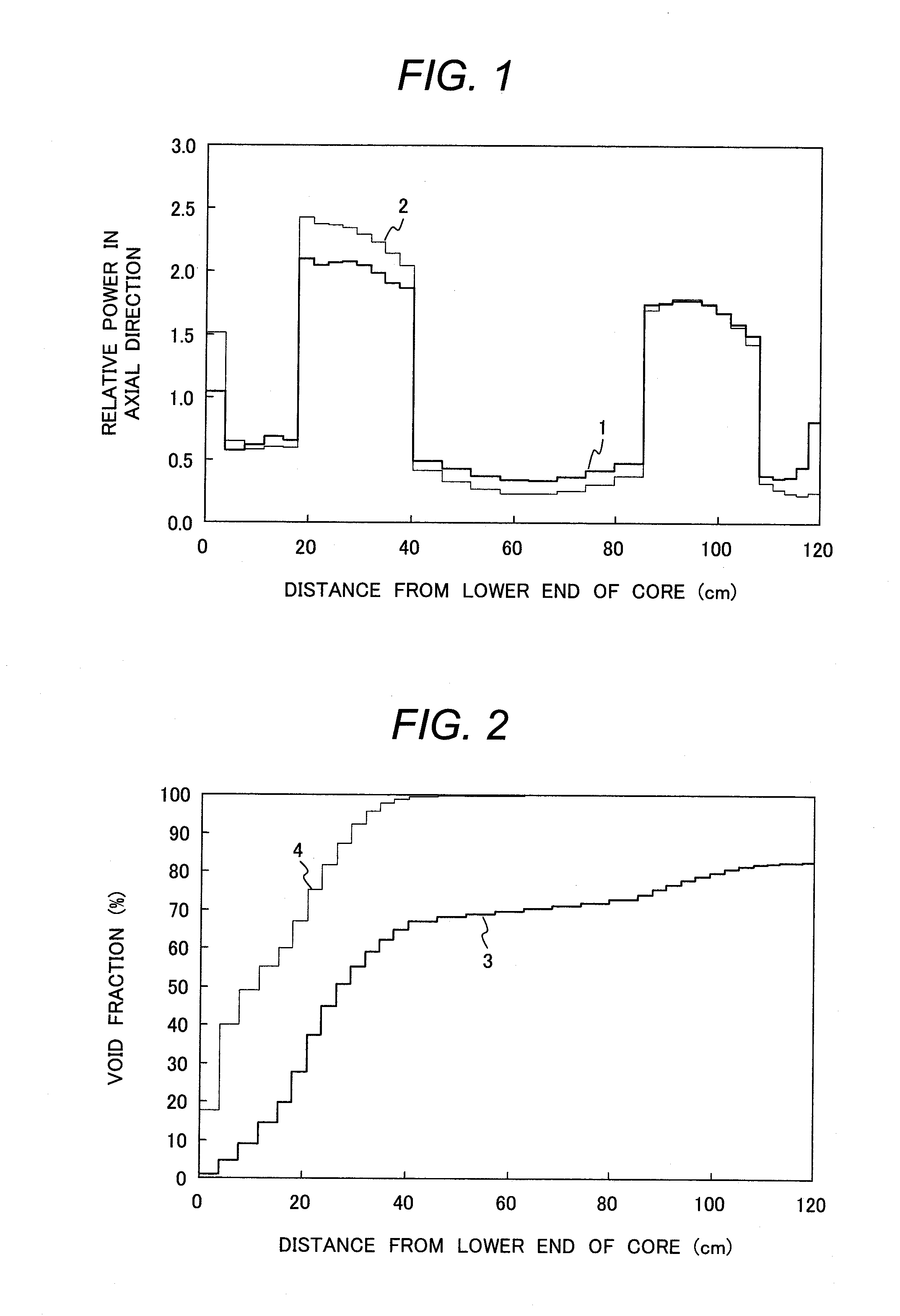
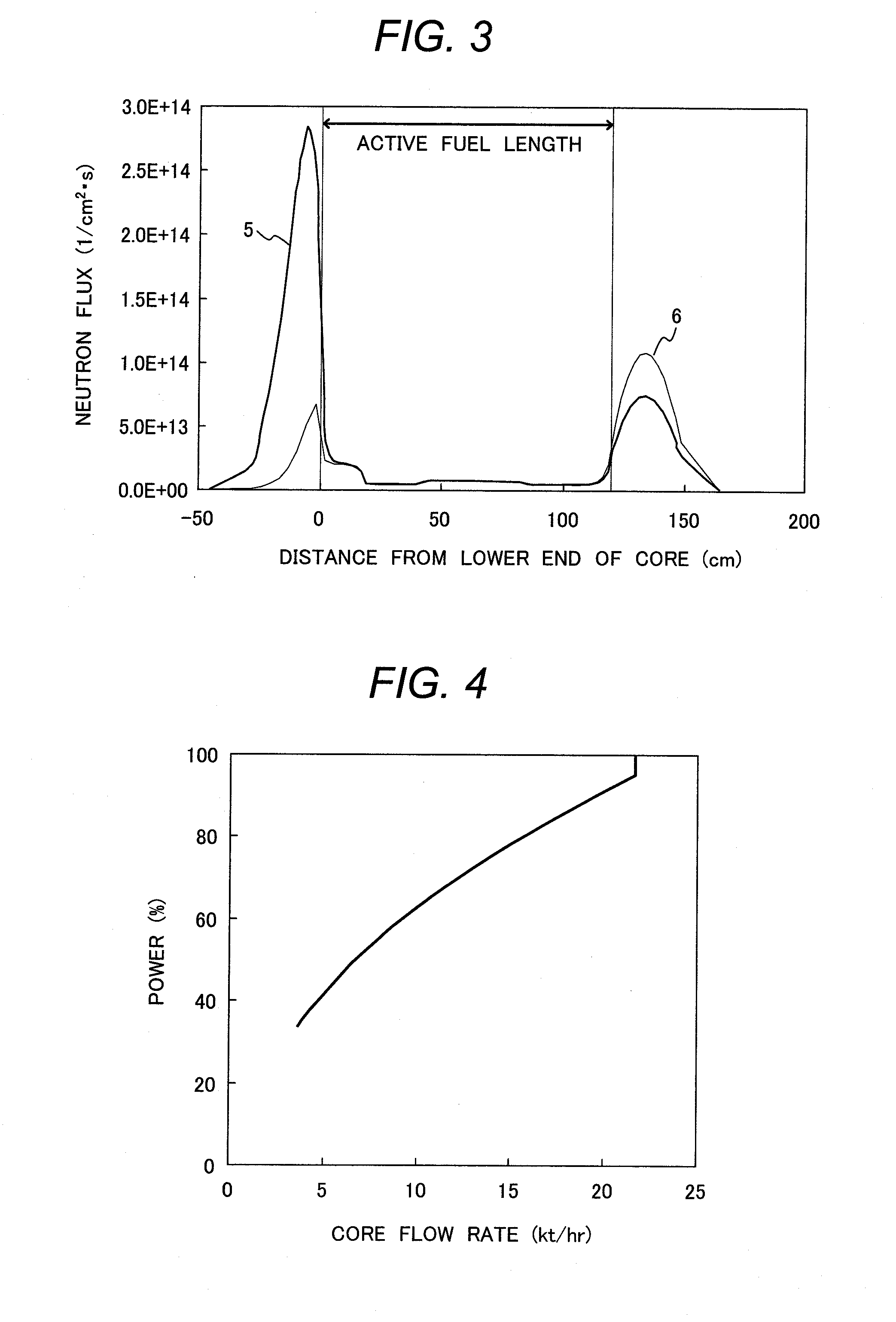
[0012]According to the present invention, a safety margin can be sufficiently maintained even with the occurrence of a compound event, in which core flow rate is suddenly dropped for some reason and all control rods cannot be inserted into the core at the same time during the operation of the light water reactor, beyond design standards. When such a compound event occurs, void fraction in the core rapidly increases, a boiling start point of coolant being slightly sub-cooled, being supplied into the core from below the core, shifts toward a lower end of the core, and the power distribution in the axial direction of the core also shifts toward the lower end of the core. Therefore, excess neutrons are shifted toward the lower end of the core. These shifted excess neutrons can be absorbed by neutron absorber in a neutron absorber filling-zone, an upper end of which is positioned in the vicinity of the lower end of the core, of a safety rod. As a result, power of the light water reactor can be automatically reduced to the power at which the fuel assemblies in the core can be cooled by the capacity of the coolant suppliable from an emergency high-pressure core flooder. Thus, a sufficient safety potential can be maintained upon the occurrence of a compound event beyond the design standards. In this way, the present invention can improve the safety margin without sacrificing the economic efficiency of the light water reactor even with the occurrence of the compound event.
[0014]According to the present invention, a safety margin can be further increased without sacrificing an economic efficiency of a light water reactor.

Problems solved by technology

Due to a fear that consumer TRU is diverted to weapons of mass destruction, there has been an increasing demand for nuclear non-proliferation and thereby restrictions on TRU recycling have been severe.

Method used


Image

  • Core of Light Water Reactor and Fuel Assembly
  • Core of Light Water Reactor and Fuel Assembly
  • Core of Light Water Reactor and Fuel Assembly

Examples


embodiment 1

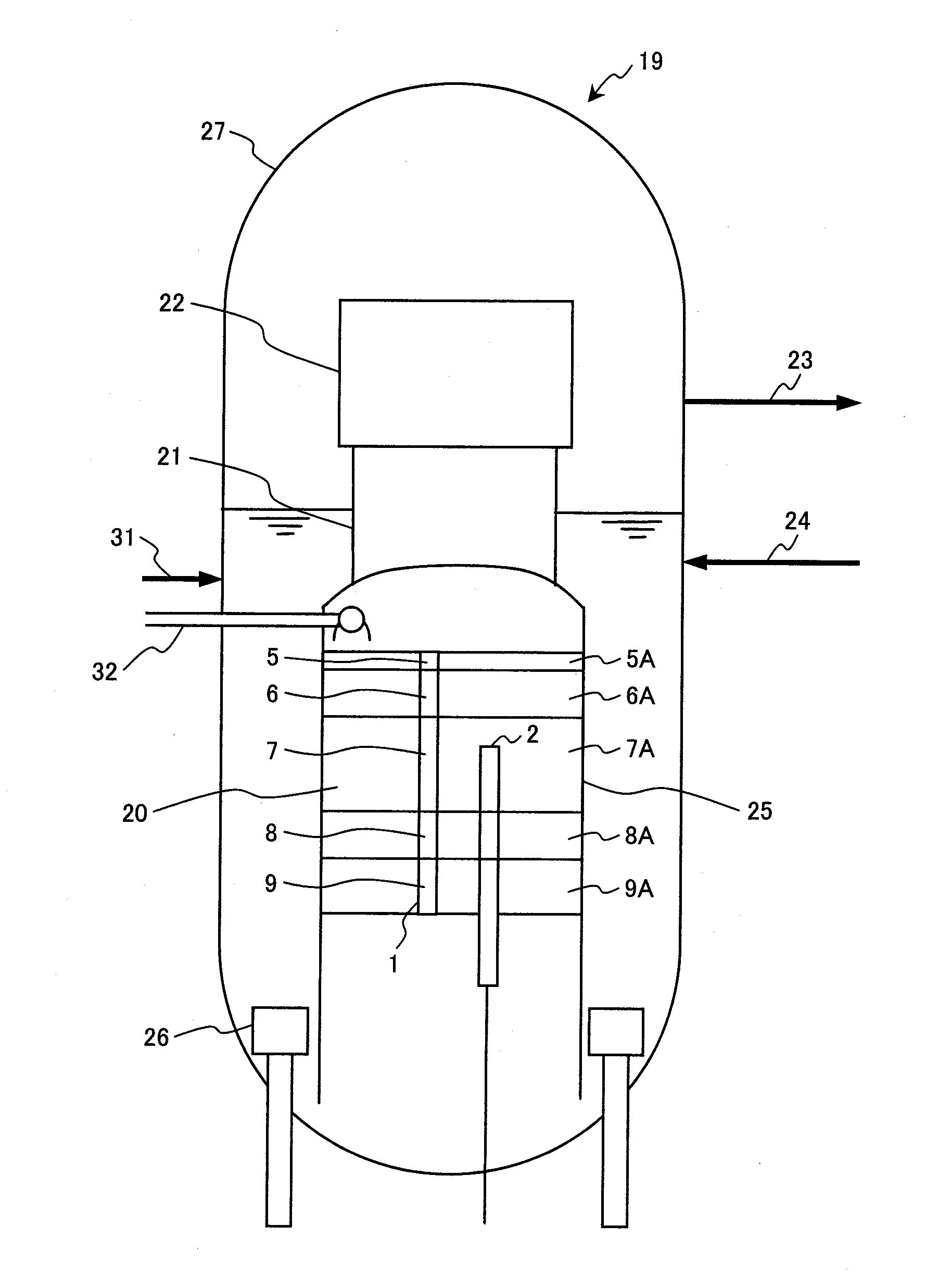
[0069]A core of a light water reactor core according to embodiment 1, which is a preferred embodiment of the present invention, is described below in detail with reference to FIGS. 11 to 19 and Table 1.

TABLE 1NuclideComposition (wt %)Np-2370.5Pu-2382.9Pu-23944.0Pu-24036.2Pu-2415.0Pu-2424.9Am-2413.6Am-242M0.2Am-2431.3Cm-2441.0Cm-2450.3Cm-2460.1

[0070]A core 20 of a light water reactor in the present embodiment is for generating an electric power of 1350 MW; however, the power scale is not limited to this value. A core having a different power scale, to which the present embodiment can be applied, can be achieved by changing the number of fuel assemblies loaded into the core 20.

[0071]An overview of a BWR, which is a light water reactor for generating an electric power of 1350 MW and to which the core 20 of the present embodiment is applied, is described based on FIG. 11. A BWR 19 has the core 20, a steam separator 21, and a stream dryer 22 disposed in a reactor pressure vessel 27. The ...

embodiment 2

[0083]A core of a light water reactor core according to embodiment 2, which is another embodiment of the present invention, is described below in detail with reference to FIGS. 20 to 22 and Table 2.

TABLE 2NuclideComposition (wt %)Np-2370.1Pu-2384.8Pu-2398.5Pu-24039.1Pu-2414.5Pu-24226.0Am-2414.5Am-242M0.2Am-2434.8Cm-2444.5Cm-2451.4Cm-2461.1Cm-2470.2Cm-2480.3

[0084]A core 20A of a light water reactor in the present embodiment has a structure in which the fuel assembly 1 in the embodiment 1 is replaced with a fuel assembly 1K shown in FIGS. 20 and 22, and other components are the same as in the embodiment 1. In the present embodiment, only components different from the embodiment 1 are described, and the descriptions of the same components as in the embodiment 1 are omitted. The core 20A is also a parfait-type core. The light water reactor to which the core 20A is applied is a BWR 19 shown in FIG. 11, in which the core 20 is replaced with the core 20A. This BWR 19 to which the core 20A ...

embodiment 3

[0095]A core of a light water reactor according to embodiment 3, which is another embodiment of the present invention, is described below in detail with reference to FIGS. 23 to 25 and Table 3.

TABLE 3NuclideComposition (wt %)Np-2370.2Pu-2385.0Pu-23913.4Pu-24040.8Pu-2414.6Pu-24221.1Am-2414.7Am-242M0.2Am-2434.1Cm-2443.6Cm-2451.1Cm-2460.8Cm-2470.2Cm-2480.2

[0096]A core 20B of a light water reactor in the present embodiment has a structure in which the fuel assemblies 1K in the core 20A in the embodiment 2 are replaced with fuel assemblies 1L described in FIGS. 24 and 25, and other components are the same as in the embodiment 2. The light water reactor to which the core 20B is applied is a BWR 19 shown in FIG. 11, in which the core 20 is replaced with the core 20B. This BWR 19 to which the core 20B is applied, has the same components, except for the core 20, as the BWR 19 to which the core of the embodiment 1 is applied. The core 20B is a core applied to a TRU disappearance reactor. The ...


PUM


Abstract

A core of a light water reactor having a plurality of fuel assemblies, which are loaded in said core, having nuclear fuel material containing a plurality of isotopes of transuranium nuclides, an upper blanket zone, a lower blanket zone, and a fissile zone, in which the transuranium nuclides are contained, disposed between the upper blanket zone and the lower blanket zone, wherein a ratio of Pu-239 in all the transuranium nuclides contained in the loaded fuel assembly is in a range of 40 to 60% when burnup of the fuel assembly is 0, sum of a height of the lower blanket zone and a height of the upper blanket zone is in a range of 250 to 600 mm, and the height of said lower blanket zone is in a range of 1.6 to 12 times the height of the upper blanket zone.

Description

CROSS REFERENCE TO RELATED APPLICATION[0001]This application is a divisional application of U.S. Application Serial No. 12 / 537,452, filed Aug. 7, 2009, the contents of which are incorporated herein by reference.CLAIM OF PRIORITY[0002]The present application claims priority from Japanese Patent application serial no. 2008-205061, filed on Aug. 8, 2008, the content of which is hereby incorporated by reference into this application.BACKGROUND OF THE INVENTION[0003]The present invention relates to a core of a light water reactor and a fuel assembly, and more particularly, to a core of a light water reactor and a fuel assembly suitable for a boiling water reactor.[0004]When actinide nuclide, which has many isotopes and is included in a nuclear fuel material in a fuel assembly loaded in a core of a light water reactor, burns in a core, the actinide nuclide to transfers among isotopes in succession by nuclear transmutation such as nuclear fission and neutron absorption. Since odd-numbered ...

Claims


Application Information

Patent Timeline
Patent Type & Authority Applications(United States)
IPC IPC(8): G21C7/00G21C3/30
CPCG21C3/326Y02E30/38G21C2003/3267G21C3/42G21C3/3267Y02E30/30
Inventor TAKEDA, RENZOMIWA, JUNICHIMORIYA, KUMIAKI
Owner HITACHI-GE NUCLEAR ENERGY LTD
Learn More