

Vial adapter
a technology of adapters and vials, applied in the field of vial adapters, can solve the problems of large amount of liquid chemical left in the vial, poor operability, and inability to adapt to such a wide range of situations
- Summary
- Abstract
- Description
- Claims
- Application Information
AI Technical Summary
Benefits of technology
Problems solved by technology
Method used
Image

Examples
first embodiment
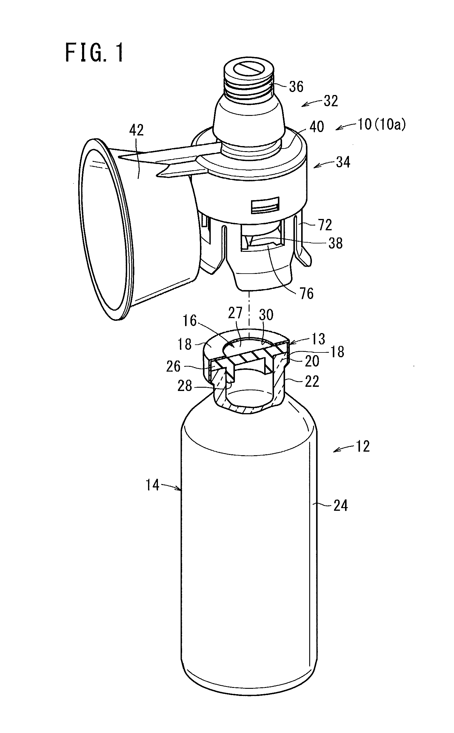
[0056]Next, a vial adapter according to the present invention will be described below, while showing preferred embodiments thereof with reference to the accompanying drawings. FIG. 1 is a perspective view showing a vial adapter 10 according to a first embodiment of the present invention, and a vial 12 for connection thereto.
[0057]First, the vial 12, as an object to which the vial adapter 10 is connected, will be described. The vial 12 contains a drug therein. The drug is a powdery or particulate solid or liquid. In the case that the drug is a powdery or particulate solid, the drug is dissolved in a dissolving liquid in order to prepare a liquid chemical, which thereafter is transferred from the vial 12 into a syringe 80 (see FIG. 6). If the drug is a liquid, the liquid is mixed with a diluting liquid (distilled water or the like) for dilution to a desired concentration, to thereby prepare a liquid chemical, which thereafter is transferred from the vial 12 into a syringe 80.
[0058]The...
second embodiment
[0116]FIG. 13 is a perspective view showing a vial adapter 110 according to a second embodiment of the present invention, and a vial 12 to be connected thereto. Since the vial 12 is of the same configuration as the vial 12 shown in FIG. 12, detailed description thereof is omitted.
[0117]Referring to FIGS. 13 to 15, the vial adapter 110 according to the present embodiment will be described. The vial adapter 110 includes a first element 112 constituting an adapter upper portion, and a second element 114 constituting an adapter lower portion. The first element 112 and the second element 114 may be produced as separate component parts, which are coupled together to form a unitary body, or such elements may be molded together integrally.
[0118]FIG. 14 is a longitudinal sectional view of the vial adapter 110, and FIG. 15 is an enlarged side view showing a distal end portion of a needle 116 and the vicinity thereof. The first element 112 is provided at one end portion (upper end portion) the...
third embodiment
[0153]Next, a third embodiment of the vial adapter according to the present invention will be described below with reference to the drawings. FIG. 17 is a longitudinal sectional view of a vial adapter 200 according to the third embodiment.
[0154]As shown in FIG. 17, the vial adapter 200 according to the third embodiment has a configuration in which the connector 118 and the valve body 122 of the vial adapter 110 in the second embodiment are replaced by a different connector 202 and a different valve body 204. Therefore, the connector 202 and the valve body 204 will be described herein, whereas parts that are common to both the vial adaptor 200 and the vial adaptor 110 of the second embodiment above are denoted by the same reference characters as used above, and overlapping descriptions of such parts are omitted.
[0155]The connector 202 of the vial adapter 200 includes the valve body 204, and a connector housing 206 in which the valve body 204 is contained (disposed).
[0156]The valve bo...
PUM
 Abstract
Description
Claims
Application Information