
Brushless fan motor and positive airway pressure breathing apparatus using the same

a brushless fan and positive airway pressure technology, which is applied in the field of motors, can solve the problems of large noise generation, and achieve the effect of reducing the noise of the brushless fan motor and the noise of the positive airway pressure breathing apparatus of the present invention

Inactive Publication Date: 2012-07-19
LEAD DATA
View PDF4 Cites 4 Cited by
  • Summary
  • Abstract
  • Description
  • Claims
  • Application Information

AI Technical Summary

Benefits of technology

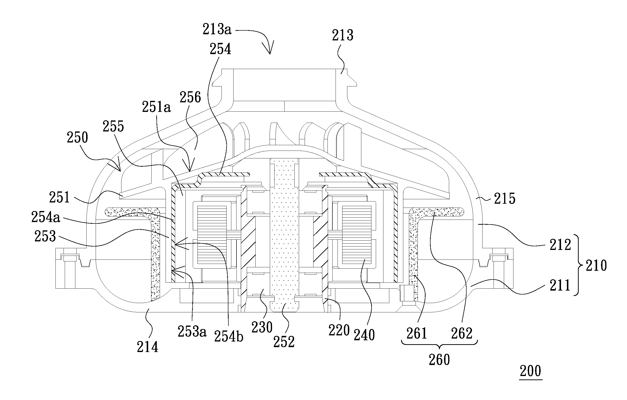
"The present invention provides a brushless fan motor that reduces noise. Additionally, the invention provides a positive airway pressure breathing apparatus that includes the brushless fan motor, which reduces noise. The brushless fan motor includes a case, tubular part, bearing, toric coil, and rotating assembly. The case has an inlet and an outlet, and the tubular part is fixed at the bottom of the case. The bearing is located in the tubular part, and the toric coil surrounds it. The rotating assembly includes a turntable, rotating shaft, loading ring, permeability metal element, and toric radial magnet. The case also includes a flow guiding member fixed at the bottom of the case. The brushless fan motor and the positive airway pressure breathing apparatus of the present invention can reduce noise and improve the quality of breathing."

Problems solved by technology

This results in an eccentric rotation when the rotating shaft 4 is rotated, and therefore, huge noise is generated when the positive airway pressure breathing apparatus is worked.

Method used


Image

  • Brushless fan motor and positive airway pressure breathing apparatus using the same
  • Brushless fan motor and positive airway pressure breathing apparatus using the same
  • Brushless fan motor and positive airway pressure breathing apparatus using the same

Examples


Embodiment Construction

[0021]The present invention will now be described more specifically with reference to the following embodiments. It is to be noted that the following descriptions of preferred embodiments of this invention are presented herein for purpose of illustration and description only. It is not intended to be exhaustive or to be limited to the precise form disclosed.

[0022]FIG. 3 is a schematic cross-sectional view of a brushless fan motor in accordance with an embodiment of the present invention, and FIG. 4 is a schematic three dimensional exploded view of FIG. 3. Referring to FIGS. 3 and 4, a brushless fan motor 200 of the present embodiment includes a case 210, a tubular part 220, at least a bearing 230, a toric coil 240 and a rotating assembly 250, wherein the tubular part 220, the bearing 230, the toric coil 240 and the rotating assembly 250 are disposed in the case 210. The case 210 has a top 213, a bottom 214 and a side wall 215 located between the bottom 214 and the top 213. The top 2...


PUM


Abstract

A brushless fan motor includes a case, a tubular part disposed in the case and fixed at a bottom of the case, at least a bearing disposed in the tubular part, a toric coil surrounding the tubular part, and a rotating assembly. The rotating assembly includes a turntable, a rotating shaft, a loading ring, a permeability metal element and a toric radial magnet. The turntable has a top surface and fan blades disposed on the top surface. The rotating shaft is disposed through the bearing and connected to the turntable. The loading ring connected to the turntable surrounds the toric coil. The permeability metal element includes an annular part fixed at an inner wall of the loading ring. The toric radial magnet is fixed at an inner wall of the annular part. A positive airway pressure breathing apparatus using the brushless fan motor is also provided.

Description

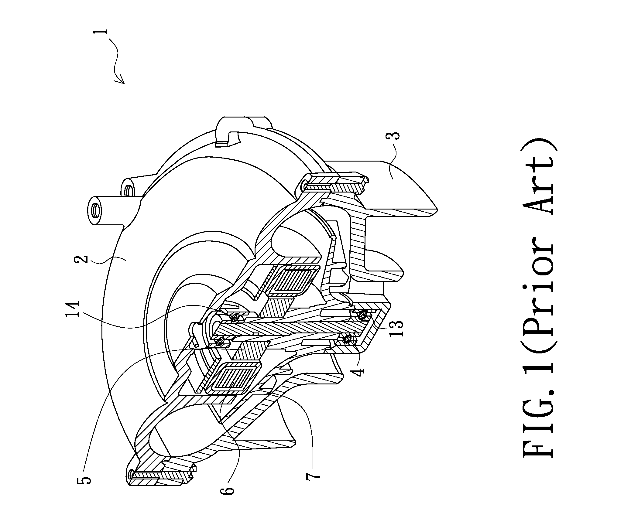
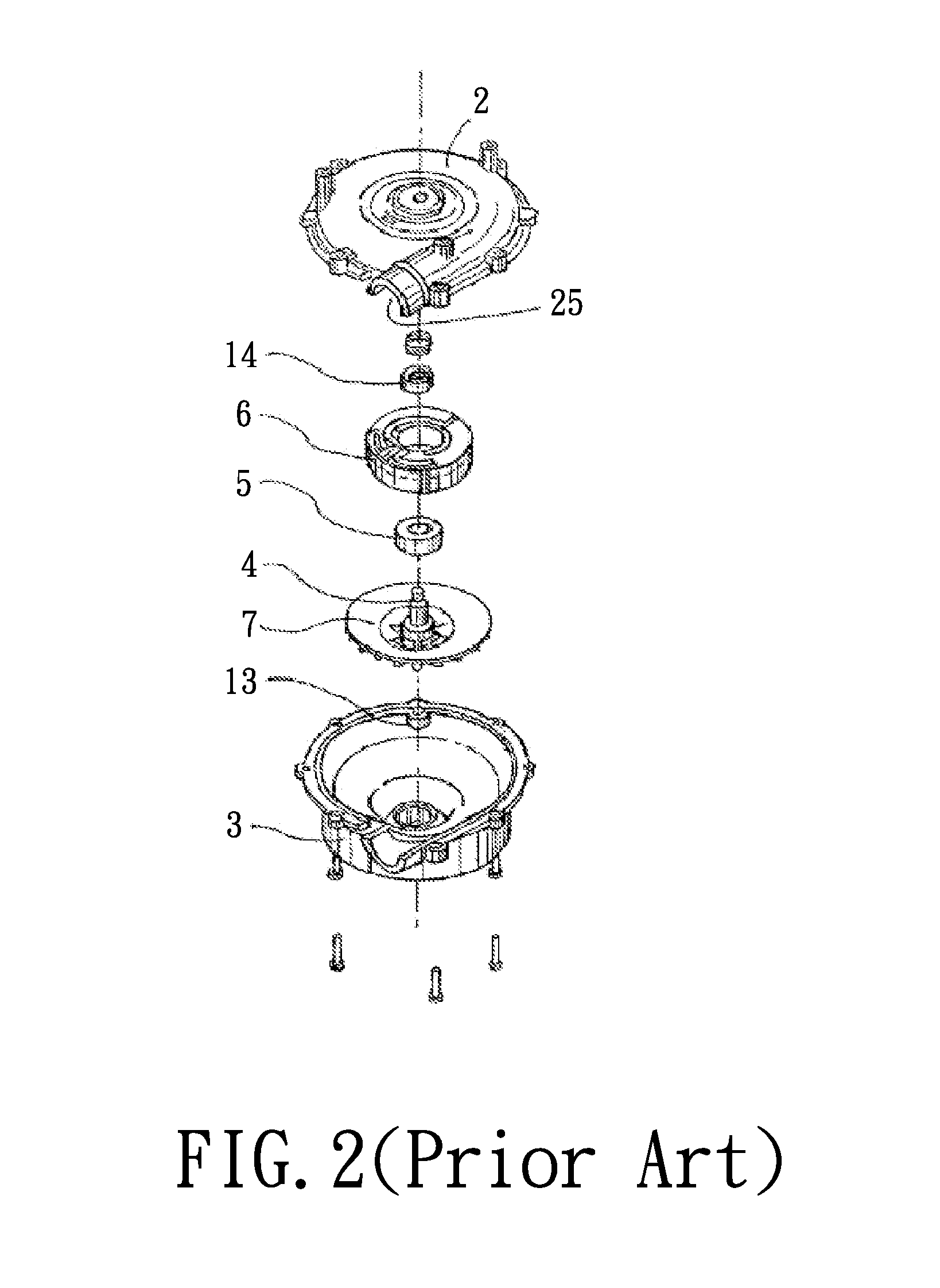
FIELD OF THE INVENTION[0001]The present invention relates to a motor, and more particularly to a brushless fan motor and a positive airway pressure breathing apparatus using the same.BACKGROUND OF THE INVENTION[0002]With the progress of medical science and technical art, living quality of modern people is improved day by day. For example, sleeping quality of a patient with obstructive sleep apnea syndrome (OSAS) can be improved by using a positive airway pressure breathing apparatus. The positive airway pressure breathing apparatus needs a fan motor to provide air to a user, so the fan motor is one of key members of the positive airway pressure breathing apparatus.[0003]FIG. 1 is a three dimensional cross sectional view of a conventional brushless fan motor of a positive airway pressure breathing apparatus, and FIG. 2 is a three dimensional exploded view of FIG. 1. Referring to FIGS. 1 and 2, a brushless fan motor 1 is disclosed in U.S. Pat. No. 6,960,854. The brushless fan motor 1 ...

Claims


Application Information

Patent Timeline
Patent Type & Authority Applications(United States)
IPC IPC(8): A61M16/00H02K21/22
CPCA61M16/0066A61M2205/42A61M16/0069H02K21/22H02K1/2733
Inventor CHENG, FENG-KUNHSIAO, CHIH-YANG
Owner LEAD DATA
Learn More