
Goat head type injection block for fracturing trees in oilfield applications

a technology of injection block and oilfield, which is applied in the direction of drilling casing, drilling pipes can solve the problems of large number of trucks, pumps, and other equipment for fracturing systems, and achieve the effect of reducing the overall height and increasing the velocity

Active Publication Date: 2012-07-19
T 3 PROPERTY HLDG
View PDF22 Cites 54 Cited by
  • Summary
  • Abstract
  • Description
  • Claims
  • Application Information

AI Technical Summary

Benefits of technology

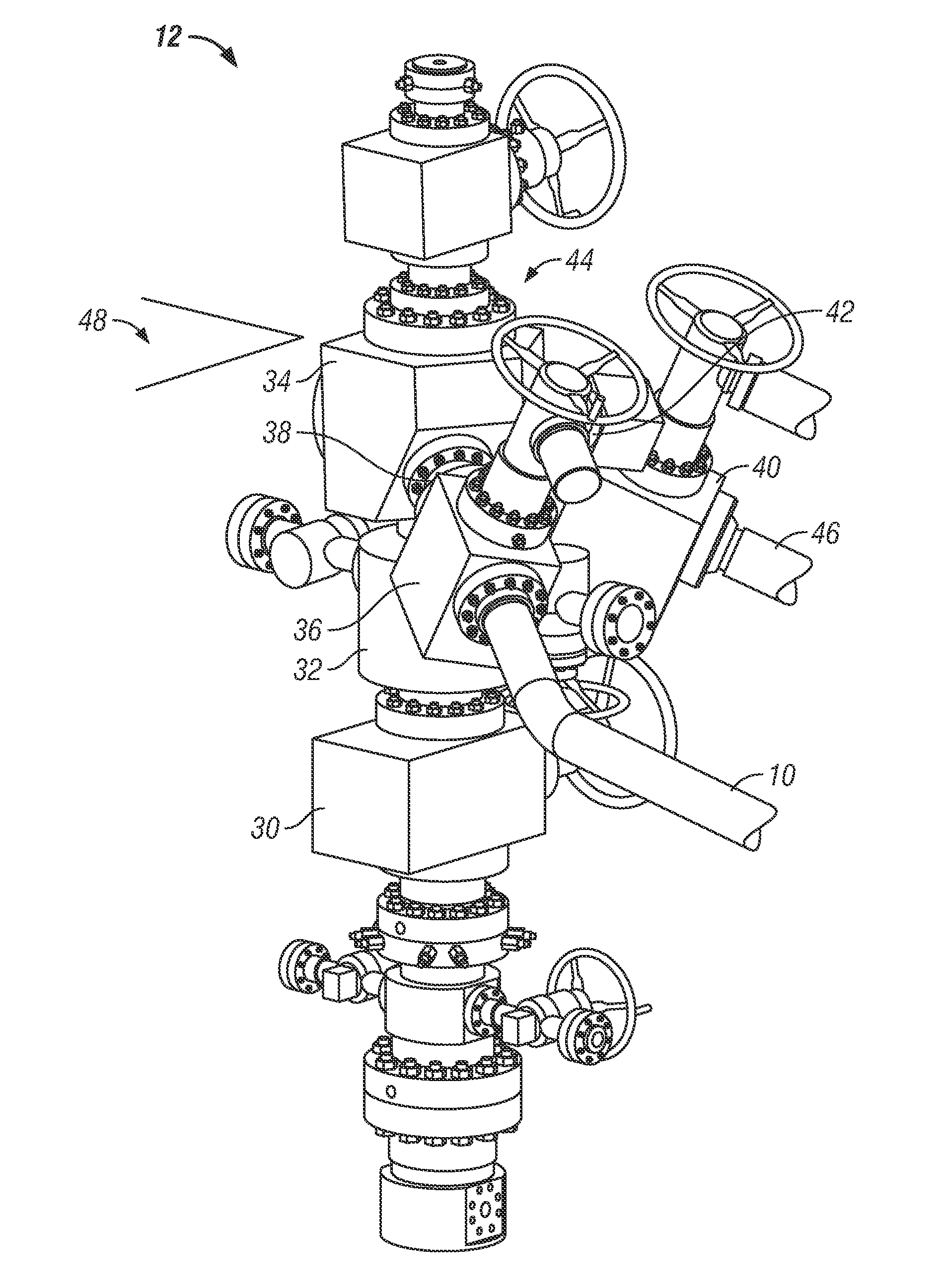
[0015]The disclosure provides a goat head, as a mixing block, for multiple fluids in oilfield applications, the goat head having a reversing directional flow, a mixing portion, wear reduction surfaces, and a restricted outlet bore. The goat head provides an underneath approach for piping, reducing the overall height, and mixes the fluids dynamically within the goat head from angled flow paths. The goat head then reverses at least a component of the fluid flow direction that enters the wellbore below the goat head and exits the goat head into the well below the goat head. The goat head contains hardened wear surfaces, including surfaces in specific zones, to resist erosion caused by the reversing directional flow. A restricted outlet bore has a cross-sectional area that is less than the sum of cross-sectional areas of the inlets to assist in creating higher velocity and streamlined flow as the fluid exits the goat head.

Problems solved by technology

At such depths, there may not be sufficient porosity and permeability to allow natural gas and oil to flow from the rock into the wellbore 22 at economic rates.
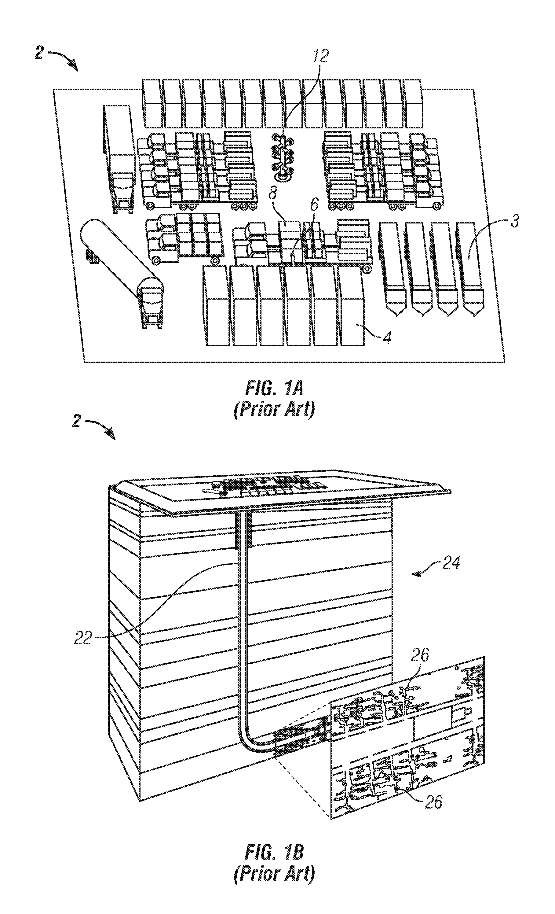
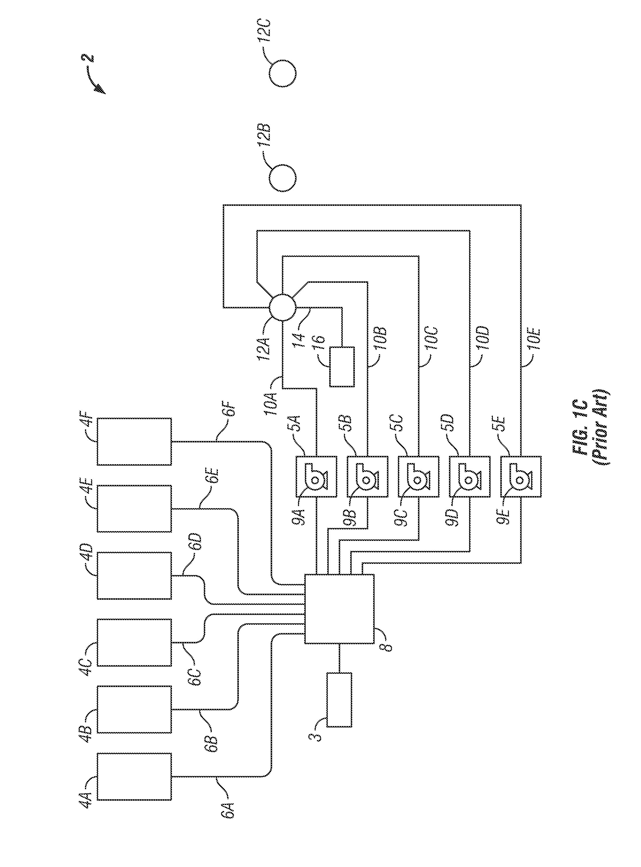
One of the significant challenges in fracturing operations is the large number of trucks, pumps, containers, hoses or other conduits, and other equipment for a fracturing system.
The difficulty of working around the wells with the large number of components also causes safety issues.
The number of assembled equipment components has raised the complexity level of the system and the ability to operate in and around the multiple wells.

Method used


Image

  • Goat head type injection block for fracturing trees in oilfield applications
  • Goat head type injection block for fracturing trees in oilfield applications
  • Goat head type injection block for fracturing trees in oilfield applications

Examples


Embodiment Construction

[0031]The Figures described above and the written description of specific structures and functions below are not presented to limit the scope of what Applicant has invented or the scope of the appended claims. Rather, the Figures and written description are provided to teach any person skilled in the art to make and use the inventions for which patent protection is sought. Those skilled in the art will appreciate that not all features of a commercial embodiment of the inventions are described or shown for the sake of clarity and understanding. Persons of skill in this art will also appreciate that the development of an actual commercial embodiment incorporating aspects of the present disclosure will require numerous implementation-specific decisions to achieve the developer's ultimate goal for the commercial embodiment. Such implementation-specific decisions may include, and likely are not limited to, compliance with system-related, business-related, government-related and other con...


PUM


Abstract

The disclosure provides a goat head, as a mixing block, for multiple fluids in oilfield applications, the goat head having a reversing directional flow, mixing portion, wear reduction surfaces, and restricted outlet bore. The goat head provides an underneath approach for piping, reducing the overall height, and mixes the fluids dynamically within the goat head from angled flow paths. The goat head then reverses at least a component of the fluid flow direction that enters the wellbore below the goat head and exits the goat head into the well therebelow. The goat head to contains hardened wear surfaces, including surfaces in specific zones, to resist erosion caused by the reversing directional flow. A restricted outlet bore has a cross-sectional area that is less than the sum of cross-sectional areas of the inlets to assist in creating higher velocity and streamlined flow as the fluid exits the goat head.

Description

CROSS REFERENCE TO RELATED APPLICATIONS[0001]Not applicable.STATEMENT REGARDING FEDERALLY SPONSORED RESEARCH OR DEVELOPMENT[0002]Not applicable.REFERENCE TO APPENDIX[0003]Not applicable.BACKGROUND OF THE INVENTION[0004]1. Field of the Invention[0005]The disclosure generally relates oilfield applications having a pumping system. More particularly, the disclosure relates to oilfield applications having a pumping system that intermixes at least two incoming fluids for fracturing operations.[0006]2. Description of the Related Art[0007]FIG. 1A is an exemplary schematic diagram of a prior art fracturing system for an oilfield fracturing operation. FIG. 1B is an exemplary schematic diagram of a prior art fracturing system, showing fractures in an underlying formation. FIG. 1C is an exemplary schematic diagram of the prior art fracturing system of FIG. 1A detailing a system for one well. The figures will be described in conjunction with each other. Oilfield applications often require pumpin...

Claims


Application Information

Patent Timeline
Patent Type & Authority Applications(United States)
IPC IPC(8): E21B43/26E21B28/00
CPCE21B21/062E21B43/26E21B43/2607
Inventor KAJARIA, SAURABHKEENE, KENDALL
Owner T 3 PROPERTY HLDG
Learn More