Drill Cuttings Methods and Systems

Active Publication Date: 2012-07-19
KMC OIL TOOLS
View PDF8 Cites 12 Cited by
  • Summary
  • Abstract
  • Description
  • Claims
  • Application Information

AI Technical Summary

Benefits of technology

[0013]The present invention overcomes the shortcomings of the prior art by providing systems and techniques for the handling of drill cuttings such that surge storage, rig buffer storage and wet and dry cuttings blending, which includes temporary storage of drill cuttings in a manner that optimizes storage capacity and the efficient and regulated movement of stored cuttings to a discharge port out of the hopper. Systems and techniques are provided that maximize available space, provide optimized surge storage to optimize the use of downstream DPCS (an

Problems solved by technology

It is common for boat schedules, delays, bad weather and the like, to require the rig operator to store cuttings until the cuttings can be transported to storage on the boat.
This is often referred to as “NPT,” an acronym for non-productive time, and is extremely expensive.
As to rig based storage, cuttings boxes on the rig can be used for this purpose, but their use requires extensive use of a crane and is a generally time consuming process.
A frequent problem faced by rig operators arises when cuttings are being generated and delivered to the DPCS at a rate faster than the DPCS can handle.
This also causes NPT and is very expensive.
No prior art is known which specifically provides “surge storage,” as a means to accommodate a DPCS, such that rapidly accumulating cuttings can be stored until the DPCS can catch up.
The general problem of high cuttings generation rates requiring surge protection has been identified by McIntyre (U.S. Pat. No. 6,530,438; “McIntyre”) although McIntyre does not contemplate use of his solution with a DPCS, and his approach is not optimized to eliminate the arching, ratholing, segregation, and/or degradation known to be associated with bulk storage of materials.
The “funnel flow” type of storage is known to be subject to ratholing (a vertical channel of movement above the opening, leaving materials in place, off to the side of the rathole), “last-in

Method used


Image

  • Drill Cuttings Methods and Systems
  • Drill Cuttings Methods and Systems
  • Drill Cuttings Methods and Systems

Examples


Embodiment Construction

[0033]The following discussion describes exemplary embodiments of the invention in detail. This discussion should not be construed, however, as limiting the invention to those particular embodiments. Practitioners skilled in the art will recognize numerous other embodiments as well.

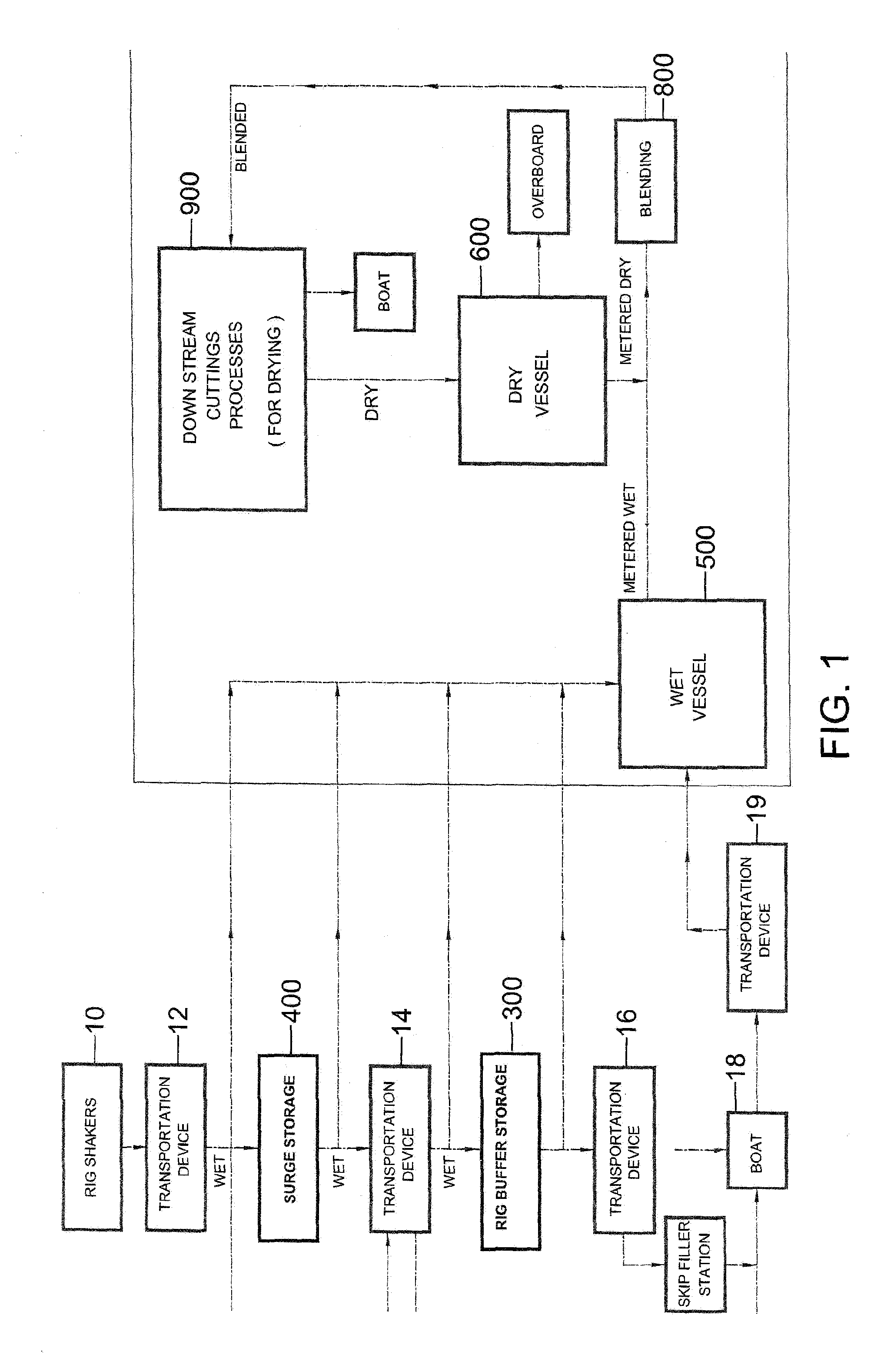
[0034]Turning now to FIG. 1, wherein exemplary embodiments of the present invention are set forth schematically. In some exemplary embodiments of the type shown in FIG. 1, methods and the apparatus, for temporarily storing cuttings, are schematically represented by the rig buffer storage 300 and also by the surge storage 400. Cuttings are transported 12 from the rig shakers 10 to such apparatus using one or more transportation devices.

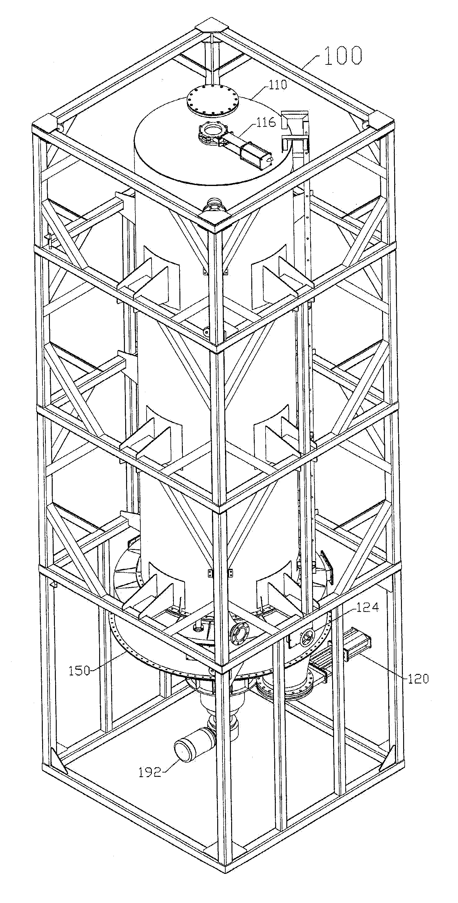
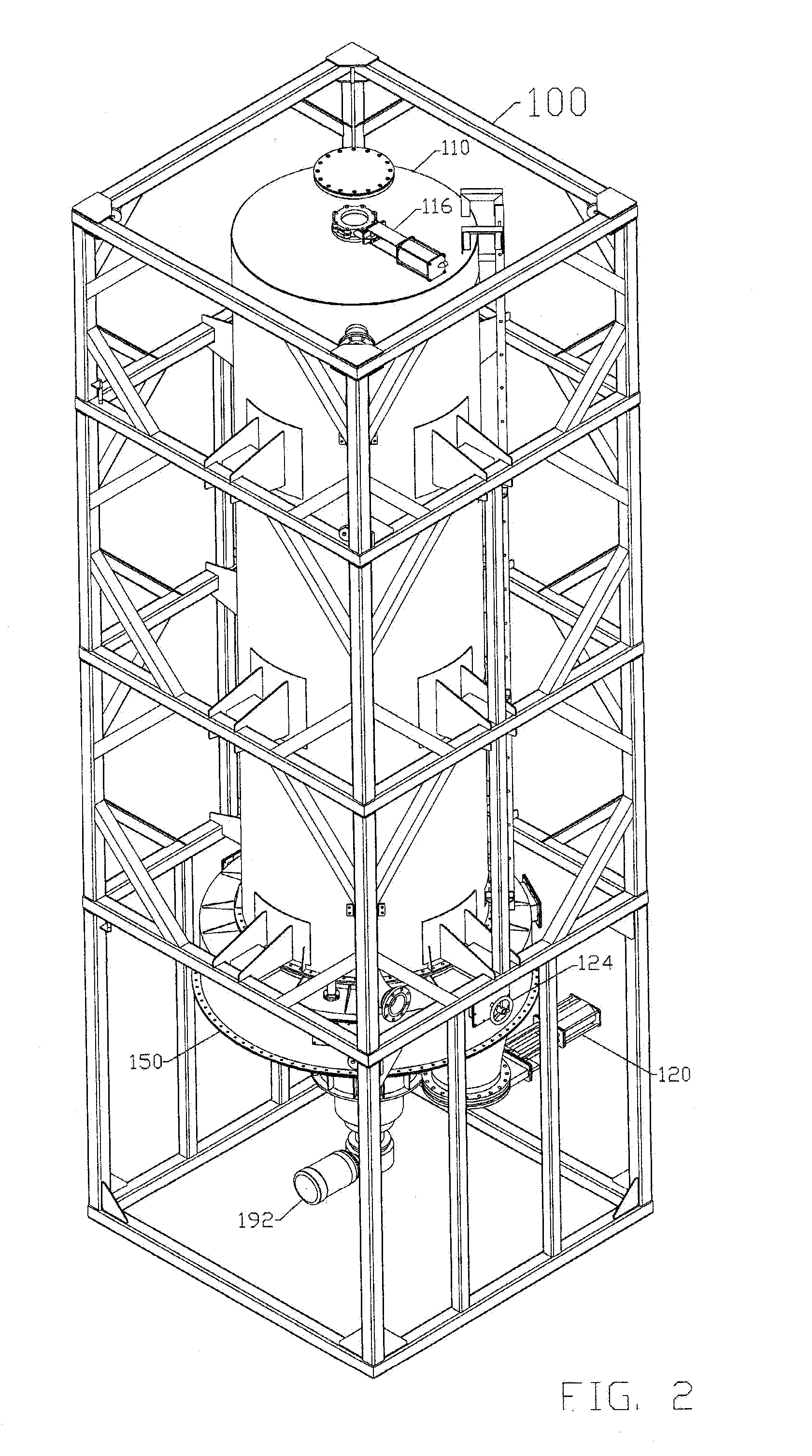
[0035]Turning now to FIGS. 2-6, in which an exemplary embodiment of a bulk storage unit 100, suitable for use as rig buffer storage and / or surge storage, is depicted and shown to include a tank 110 attached to a mass flow feeder 150, both being mounted in a frame 112. The cu...


PUM


Abstract

Systems and techniques, including a circle feeder, for the handling of drill cuttings, providing surge storage, rig buffer storage and wet and dry cuttings blending, including temporary storage of drill cuttings, optimizing storage capacity and the efficient and regulated movement of stored cuttings to a discharge port out of the hopper. Systems and techniques, maximize available space, provide optimized surge storage to optimize the use of downstream DPCS (and other transportation devices), provide optimized rig based storage and discharge, minimize or eliminate the occurrence of ratholing, bridging, degradation, segregation, and dehydration within the hopper, control and regulate the flow of cuttings from the hopper to the discharge port from the hopper, and provide metered discharge from the hopper storage, particularly when one hopper is discharging wet cuttings and a second hopper is discharging dry cuttings, and it is desirable to blend the wet and dry cuttings after such metered discharge.

Description

BACKGROUND OF THE INVENTION[0001]1. Field of the Invention[0002]The present invention is directed to the handling, storage and disposal of earthen drill cuttings circulated out of an oil and gas well being drilled.[0003]2. Description of Related Art[0004]Drill cuttings are typically wet with drilling fluid and lose only a portion of the fluids on the rig shakers, leaving wet cuttings to address in an appropriate manner, consistent with economic constraints and environmental considerations, especially in an offshore environment. Drying processes include several well known techniques for drying the cuttings, which is often desirable, especially if any overboard disposal is intended.[0005]Various transportation devices exist for moving the cuttings to various destinations, for further treatment and / or disposal, including, without implied limitation, gravity-drawn movement along troughs, augers (screw conveyors), vacuum systems, where the cuttings are pulled through conduits by creating...

Claims


Application Information

Patent Timeline
IPC IPC(8): E21B21/06
CPCB65D88/26E21B21/066B65D90/587B65D88/60
Inventor ADDISON, CRAIG WILLIAMCARLSON, KENNETH RICHARDFARRAR, JOSEPH DANIELLYMAN, PERRY
Owner KMC OIL TOOLS
Why Eureka
Try Eureka