Lighting device

a technology of light-emitting diodes and heat-emitting devices, which is applied in the direction of lighting and heating apparatus, semiconductor devices for light sources, and support devices for light-emitting devices. it can solve the problems of reducing the effectiveness of the heat-emitting device on the board, poor thermal conductivity of conventional light-emitting diodes (leds), and inability to easily dissipate hot air inside the cavity, so as to achieve the effect of improving

Inactive Publication Date: 2012-07-19
LITE ON TECH CORP +1
View PDF2 Cites 8 Cited by
  • Summary
  • Abstract
  • Description
  • Claims
  • Application Information

AI Technical Summary

Benefits of technology

[0006]The present invention provides a lighting device having an improved heat dissipating structure.

Problems solved by technology

Many conventional light emitting diode (LED) designs suffer poor thermal conductivity, particularly on and around the circuit boards.
Also, many conventional lighting devices have their LEDs disposed in a cavity, thus the hot air being generated inside the cavity cannot be dissipated easily.
In addition, the housing of the conventional lighting devices often blocks the air to flow, thereby reducing the effectiveness of their onboard heat dissipating devices.

Method used


Image

  • Lighting device
  • Lighting device
  • Lighting device

Examples


Embodiment Construction

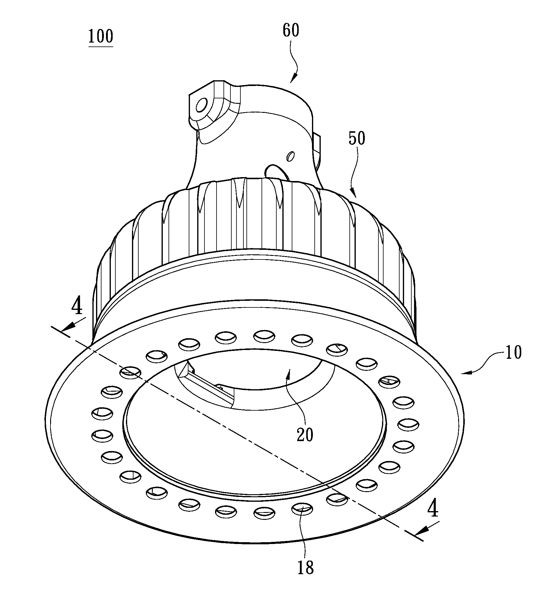
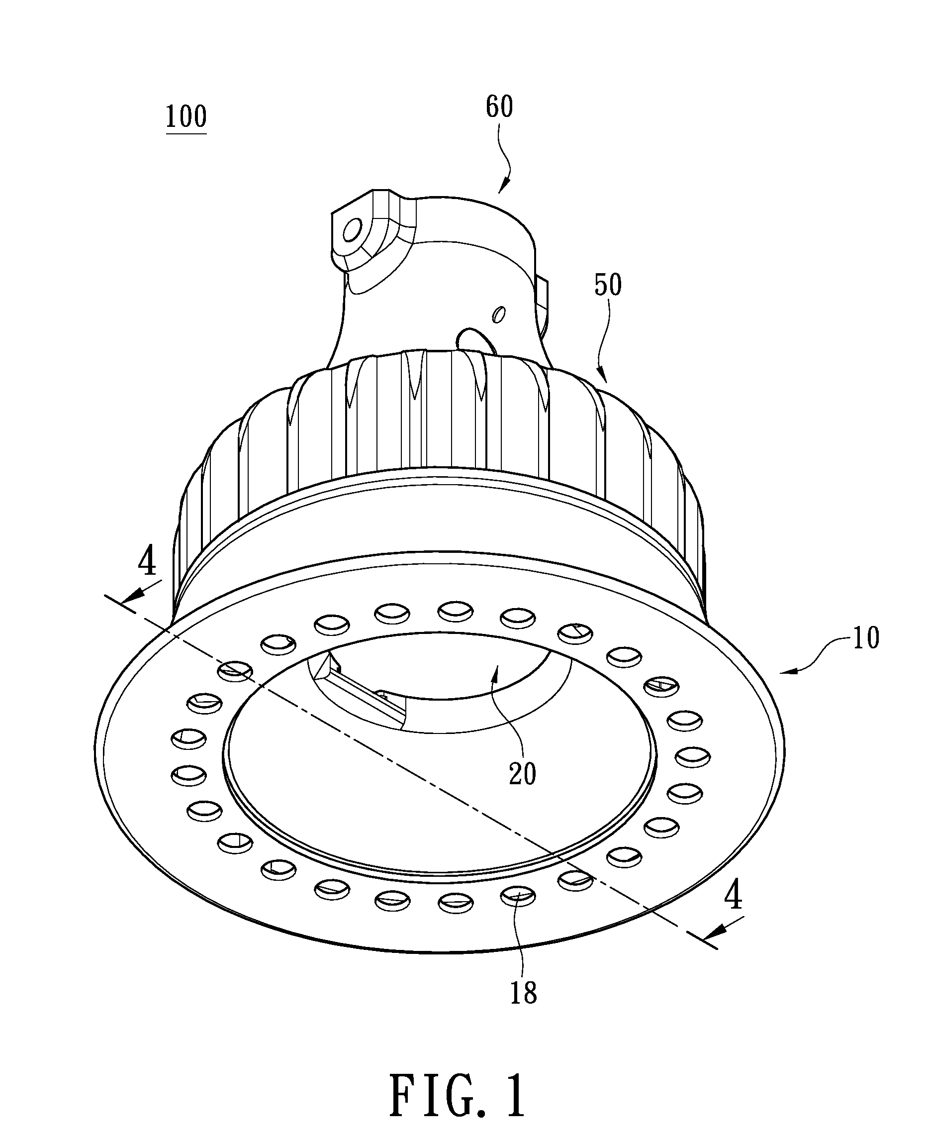
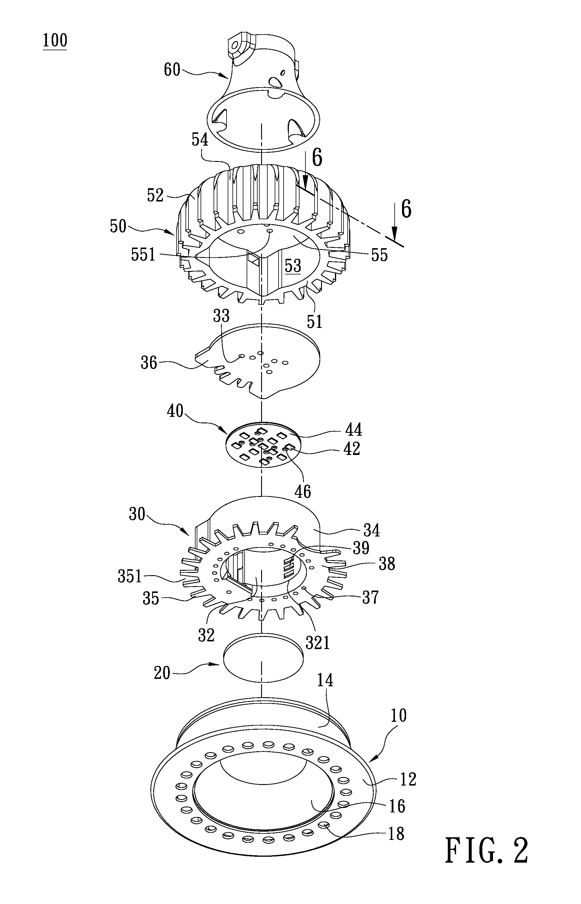
[0018]Please note that, in the following description, the referenced directions (up, down, left, right, front or rear) are merely for explaining the appended drawings, rather than being used to restrict the scope of the present invention. Please refer to FIGS. 1 to 4. A disclosed lighting device 100 comprises a cover 10, a cover plate 20, a housing 30, a light source module 40, a heat sink 50, and a holder 60.

[0019]The housing 30 comprises a first shell portion 32, a second shell portion 34, a first plate portion 36, and a connecting portion 38 and may be made of metallic or other thermal conductive material. The first shell portion 32 and the second shell portion 34 are barrel-shaped. The second shell portion 34 encircles the first shell portion 32 with a specified distance in-between. Therefore, the housing 30 is a double-walled structure. The first plate portion 36 is disposed on one end (being the top end) of the first shell portion 32 and the second shell portion 34, to cover t...


PUM


Abstract

A lighting device includes a light source module and a housing mated to a heat sink and covered by a cover. The housing has a first shell portion encircled by an inner sidewall of the heat sink. Alternatively, the housing may further has a second shell portion arranged between the first shell portion and the inner sidewall of the heat sink. The respective ends of the first and second shell portions are covered by a first plate portion and a connecting portion. A cavity is defined by the first shell portion and the first plate portion for accommodating the light source module. A plurality of first thru-holes, second thru holes, third thru holes, fourth thru-holes, and fifth thru holes are formed on the circuit board, the connecting portion, the cover, the first shell portion, and the first plate portion, respectively.

Description

BACKGROUND OF THE INVENTION[0001]1. Field of the Invention[0002]The present invention relates to a lighting device; more particularly, to a lighting device having a plurality of heat dissipating holes on a housing thereof for improved heat dissipation.[0003]2. Description of Related Art[0004]Many conventional light emitting diode (LED) designs suffer poor thermal conductivity, particularly on and around the circuit boards. Also, many conventional lighting devices have their LEDs disposed in a cavity, thus the hot air being generated inside the cavity cannot be dissipated easily. In addition, the housing of the conventional lighting devices often blocks the air to flow, thereby reducing the effectiveness of their onboard heat dissipating devices.[0005]To address the above issues, the inventors propose the following solution.SUMMARY OF THE INVENTION[0006]The present invention provides a lighting device having an improved heat dissipating structure.[0007]The present invention has the f...

Claims


Application Information

Patent Timeline
Patent Type & Authority Applications(United States)
IPC IPC(8): F21V29/00F21V21/00
CPCF21V29/004F21Y2101/02F21Y2105/001F21V29/83F21V29/507F21V29/773F21V29/505F21Y2105/10F21Y2115/10
Inventor LEE, TSUNG-CHIHSU, SHIH-CHANG
Owner LITE ON TECH CORP
Why Eureka
Try Eureka