Power connector

a technology of power connectors and connectors, applied in the direction of connection contact materials, coupling device connections, electric discharge lamps, etc., can solve the problems of poor heat dissipation of power receptacles, complex and difficult manufacture of such contacts,

Inactive Publication Date: 2011-08-16
ALLTOP ELECTRONICS SU ZHOU
View PDF5 Cites 9 Cited by
  • Summary
  • Abstract
  • Description
  • Claims
  • Application Information

AI Technical Summary

Benefits of technology

[0002]The present invention relates to a power connector, more particularly to a power connector for being mounted on a circuit board and with improved heat dissipation structure.

Problems solved by technology

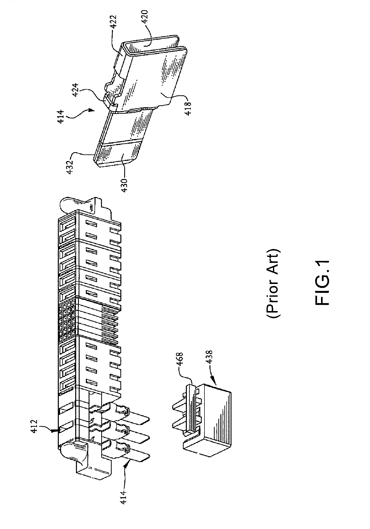
However, the configuration of such contacts 414 are complex and difficult for manufacture.
Parts of the contacts 414 exposed to the outside must be decreased, which results in poor heat dissipation of the power receptacle.

Method used


Image

  • Power connector
  • Power connector
  • Power connector

Examples


Embodiment Construction

[0020]In the following description, numerous specific details are set forth to provide a thorough understanding of the present invention. However, it will be obvious to those skilled in the art that the present invention may be practiced without such specific details. In other instances, well-known circuits have been shown in block diagram form in order not to obscure the present invention in unnecessary detail. For the most part, details concerning timing considerations and the like have been omitted inasmuch as such details are not necessary to obtain a complete understanding of the present invention and are within the skills of persons of ordinary skill in the relevant art.

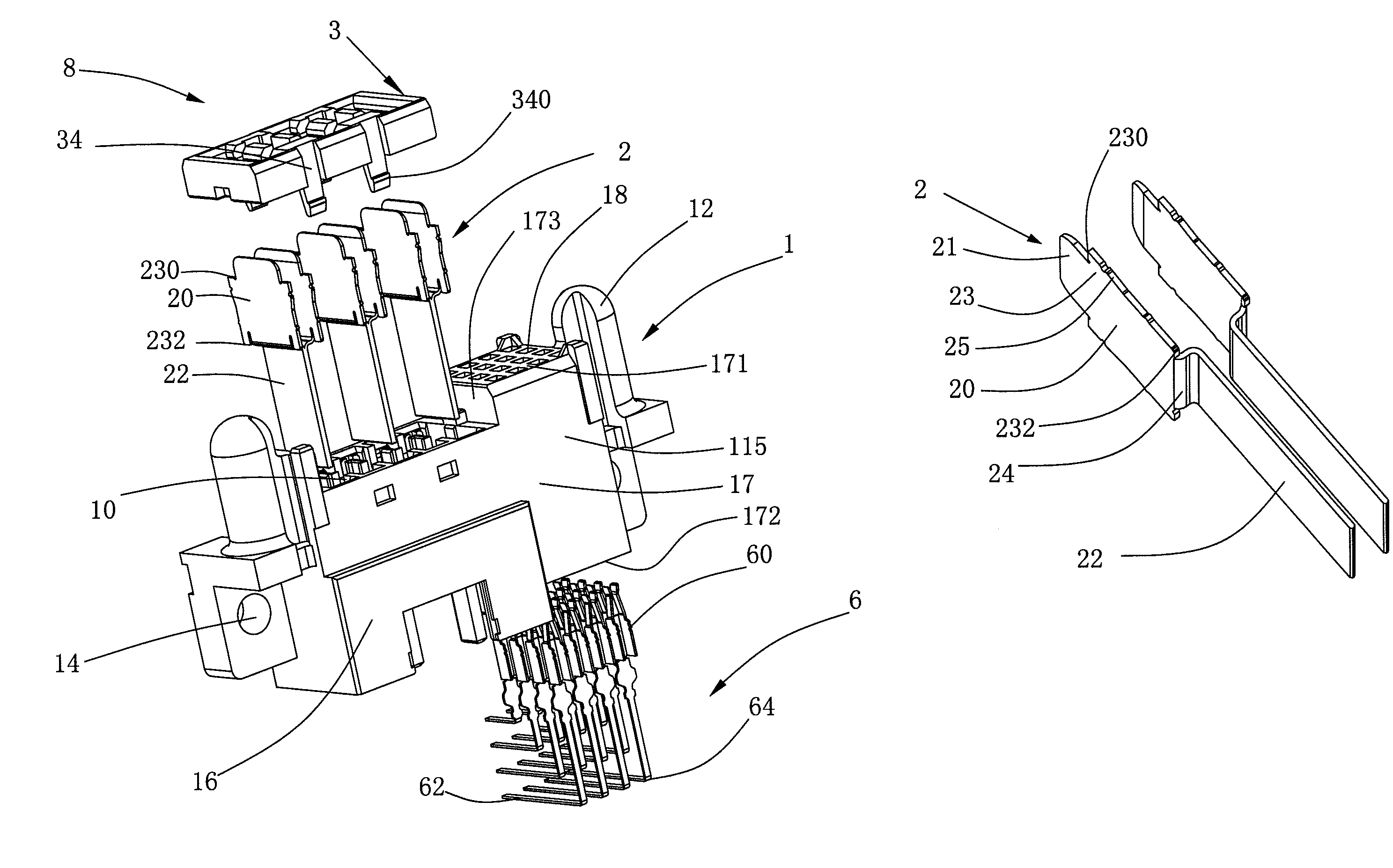
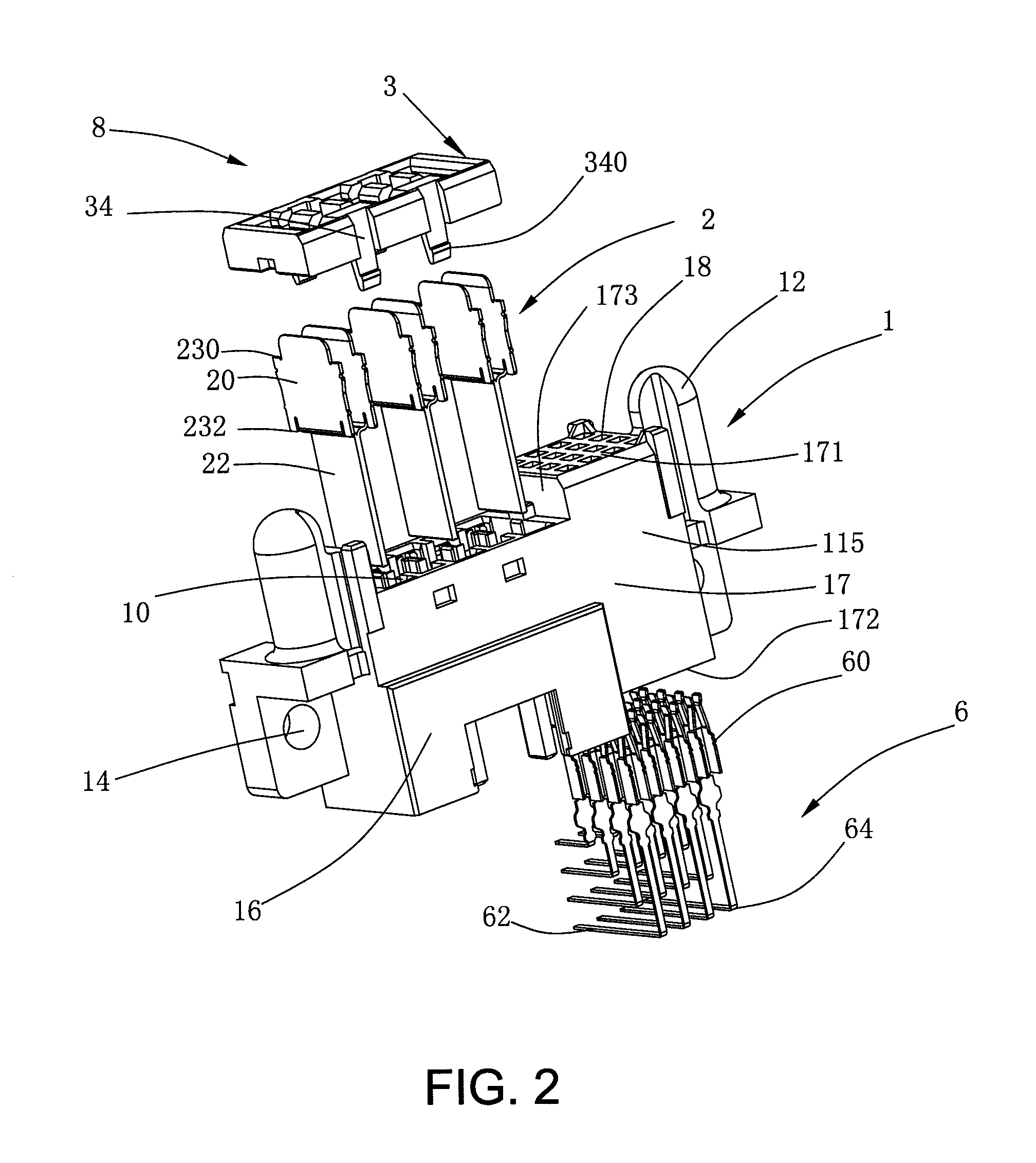
[0021]Referring to FIGS. 2-4, the present invention relates to a power connector 8 mounted on a printed circuit board (not shown) for mating with a corresponding connector (not shown) for power transmission. The power connector 8 includes an insulative housing 1, a plurality of first and second contacts 2, 6 re...


PUM


Abstract

A power connector includes an insulative housing, a number of contacts retained in the insulative housing and a spacer fixed to the insulative housing. The insulative housing includes a mating surface, an end surface opposite to the mating surface and a plurality of first passageways extending through the mating and the end surfaces. A depression and a cavity are recessed into the insulative housing from the mating surface and the end surface, respectively. Each first contact includes a main portion received in the corresponding first passageway and a tail portion located at the cavity in condition that at least one side wall of the tail portion is exposed to the outside for excellent heat dissipation.

Description

BACKGROUND OF THE INVENTION[0001]1. Field of the Invention[0002]The present invention relates to a power connector, more particularly to a power connector for being mounted on a circuit board and with improved heat dissipation structure.[0003]2. Description of Related Art[0004]Designers of electronic circuits generally are concerned with two basic circuit portions, the logic or signal portion and the power portion. In designing logic circuits, the designer usually does not have to take into account any changes in electrical properties, such as resistance of circuit components, that are brought about by changes in conditions, such as temperature, because current flows in logic circuits are usually relatively low. However, power circuits can undergo changes in electrical properties because of the relatively high current flows, for example, on the order of 30 amps or more in certain electronic equipment. Consequently, connectors designed for use in power circuits must be capable of dis...

Claims


Application Information

Patent Timeline
Patent Type & Authority Patents(United States)
IPC IPC(8): H01R25/00
CPCH01R13/055H01R12/712H01R13/506H01R13/4367
Inventor YU, WANG-I
Owner ALLTOP ELECTRONICS SU ZHOU
Why Eureka
Try Eureka