Shell heat dissipating structure of small form-factor pluggable transceiver

a plug-in, small technology, applied in the direction of instruments, lighting and heating apparatus, semiconductor/solid-state device details, etc., can solve the problems of heat dissipation, heat dissipation cannot be resolved, and needs to be improved, so as to improve the heat dissipation structure of the qsfp, improve the efficiency of heat dissipation, and enhance the effect of forced heat convection

Active Publication Date: 2021-07-27
JESS-LINK PRODUCTS
View PDF34 Cites 7 Cited by
  • Summary
  • Abstract
  • Description
  • Claims
  • Application Information

AI Technical Summary

Benefits of technology

[0005]The main objective of the present invention is to provide a shell heat dissipating structure of a small form-factor pluggable transceiver, which further improves the heat dissipating structure of the QSFP and increases the efficiency of heat dissipation through enhanced forced heat convection.

Problems solved by technology

However, with the increasing transmission speed, the high temperature is caused during the operation and results in the issue of heat dissipation.
Because the issue of heat dissipation cannot be resolved by the fin design, it still needs to be improved.

Method used


Image

  • Shell heat dissipating structure of small form-factor pluggable transceiver
  • Shell heat dissipating structure of small form-factor pluggable transceiver
  • Shell heat dissipating structure of small form-factor pluggable transceiver

Examples


first embodiment

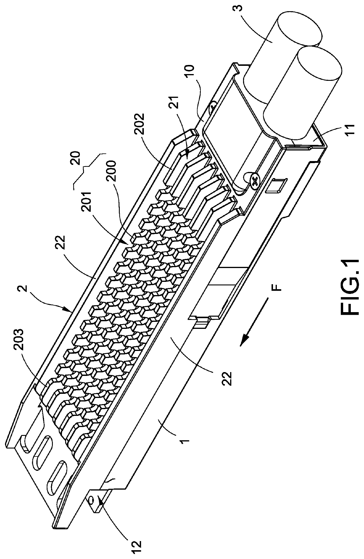
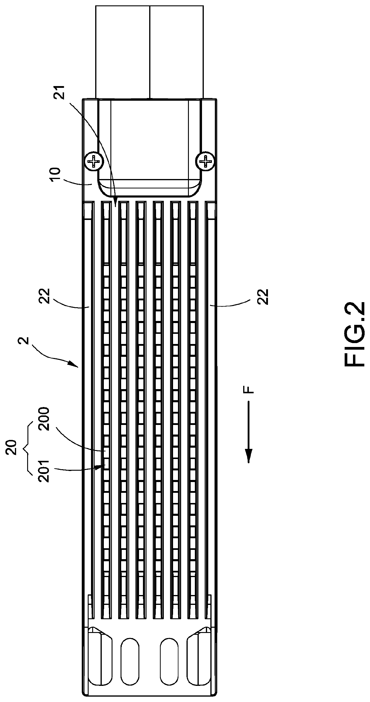
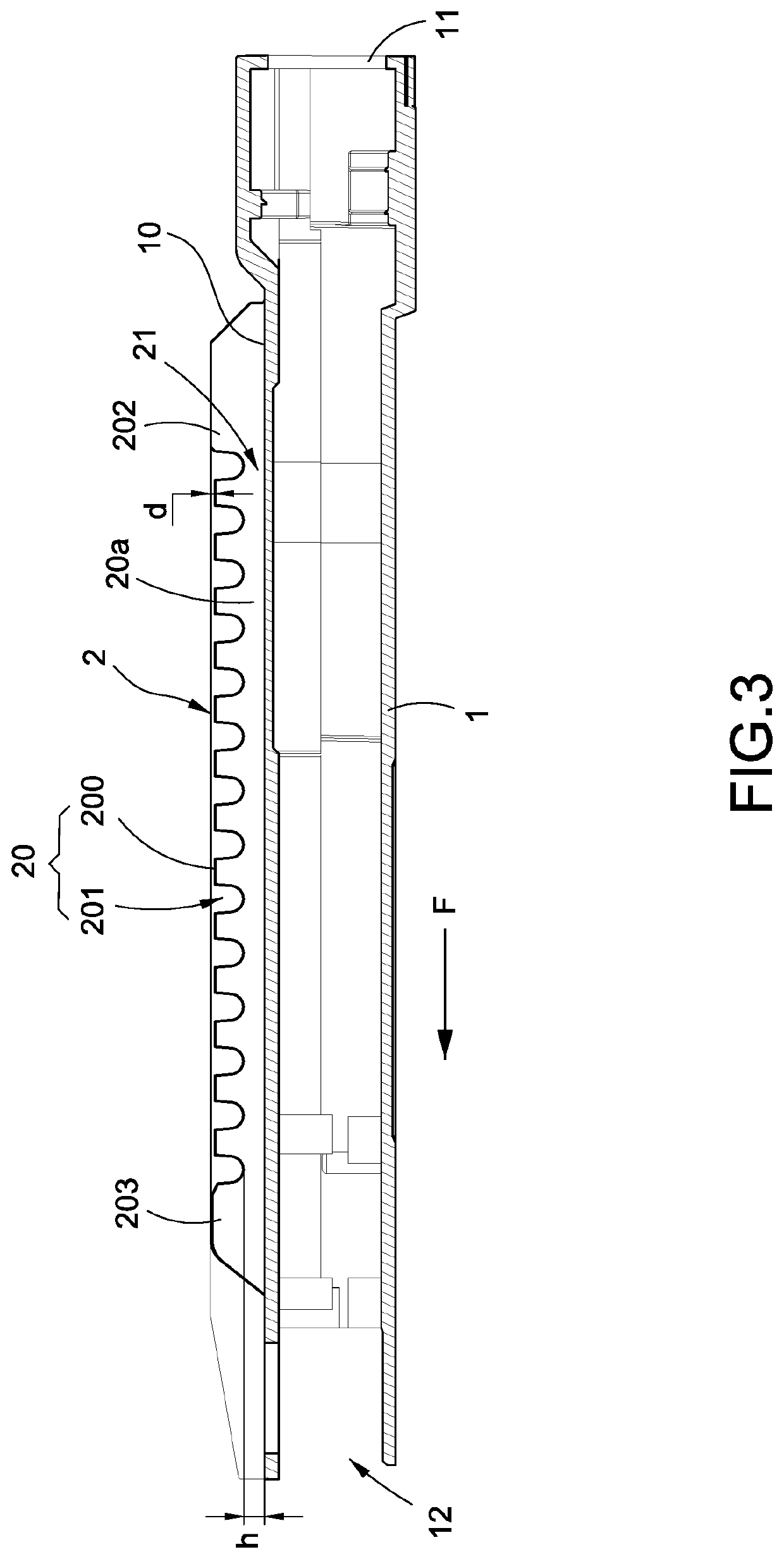
[0013]Please refer to FIGS. 1-3, which are the perspective view, the top view, and the side cross-sectional view of the shell heat dissipating structure according to the present invention, respectively. The present invention provides a shell heat dissipating structure of a small form-factor transceiver, which comprises a hollow shell 1 and a heat dissipating structure 2 disposed on the hollow shell 1.

[0014]The hollow shell 1 may be made of aluminum or aluminum alloy which has higher thermal conductivity. The hollow shell 1 has a bar-like shape according to the general specifications and is hollow as shown in FIG. 3, which can receive the electronic device (not shown) such as the QSFP and the printed circuit board. The hollow shell 1 has a setting surface 10 disposed on the outside; the setting surface 10 is formed along the extending direction F of the hollow shell 1 having the bar-like shape. Further, the hollow shell 1 has two ports 11, 12. The port 11 is used for electrical conne...

second embodiment

[0017]Furthermore, FIGS. 4 and 5 are the perspective exploded view and the perspective assembled view of the shell heat dissipating structure according to the present invention, respectively. The heat dissipating structure 2 in the present invention further comprises an air shroud 13 disposed on the heat dissipating structure 2. The air shroud 13 mainly covers the channels 21 up such that the channels 21 and the air shroud 13 form together the wind tunnels to facilitate the air flow. In the current embodiment of the present invention, the air shroud 13 crosses and covers the two stop plates 22 to include the tops of the respective channels 21, and can be flush with the first guiding portion 202 and the second guiding portion 203. In a preferable design, the air shroud 13 can cover only the area where the fins 20 have the projecting portions 200 and the recess portions 201, exposing the first guiding portions 202 and the second guiding portions 203 of the respective fins 20. In this ...


PUM


Abstract

A shell heat dissipating structure of a small form-factor transceiver includes a hollow shell and a heat dissipating structure. The hollow shell has a setting surface disposed on the outside; the setting surface is formed along an extending direction of the hollow shell. The heat dissipating structure has plural fins formed along the extending direction of the hollow shell and spaced on the setting surface; a plurality of channels is formed among the fins. Each of the fins is formed by plural projecting portions and recess portions disposed along the extending direction and alternated continuously such that the channels among the fins communicate with each other through the recess portions.

Description

BACKGROUND OF THE INVENTIONField of the Invention[0001]The present invention relates to an electrical connector, and in particular, to a shell heat dissipating structure of a small form-factor pluggable transceiver.Description of Prior Art[0002]The quad small form-factor pluggable (QSFP) transceiver is a small hot plugging optical transceiver which is used in optical communication applications such as telecommunications and network communications and is one of the optical devices complying with the standard specifications.[0003]However, with the increasing transmission speed, the high temperature is caused during the operation and results in the issue of heat dissipation. As for the existing QSFP, there is no heat dissipating structure disposed or only plural fins disposed on the external surface thereof. Because the issue of heat dissipation cannot be resolved by the fin design, it still needs to be improved.[0004]In view of this, the inventor pays special attention to research wit...

Claims


Application Information

Patent Timeline
Patent Type & Authority Patents(United States)
IPC IPC(8): F28D1/02H01L23/367F28F9/02F28F9/22F28D21/00
CPCF28D1/0233H01L23/3675F28D2021/0028F28F9/0229F28F9/22F28F2215/00G02B6/4246G02B6/4269H01L23/3672H01L23/467
Inventor CHEN, CHUN-HUA
Owner JESS-LINK PRODUCTS
Why Eureka
Try Eureka