Electrical connector having heat-dissipation structure

a technology of heat dissipation structure and electric connector, which is applied in the direction of electrical equipment, printed circuits, coupling device connections, etc., can solve the problems of increasing the temperature of the card edge connector, adversely affecting the electrical connection between the card edge connector and the electrical card, and cannot be quickly dissipated, so as to achieve the effect of improving the heat dissipation structur

Inactive Publication Date: 2005-12-06
HON HAI PRECISION IND CO LTD
View PDF5 Cites 7 Cited by
  • Summary
  • Abstract
  • Description
  • Claims
  • Application Information

AI Technical Summary

Benefits of technology

[0007]An object of the present invention is to provide a card edge connector having an improved heat-dissipation structure through which heat generated therein can be quickly dissipated.

Problems solved by technology

Heat generated in the card edge connector thus cannot be quickly dissipated through the openings of the passageways in the mating face of insulative housing, thereby increasing the temperature of the card edge connector and adversely affecting the electrical connection between the card edge connector and the electrical card.

Method used


Image

  • Electrical connector having heat-dissipation structure
  • Electrical connector having heat-dissipation structure
  • Electrical connector having heat-dissipation structure

Examples


Embodiment Construction

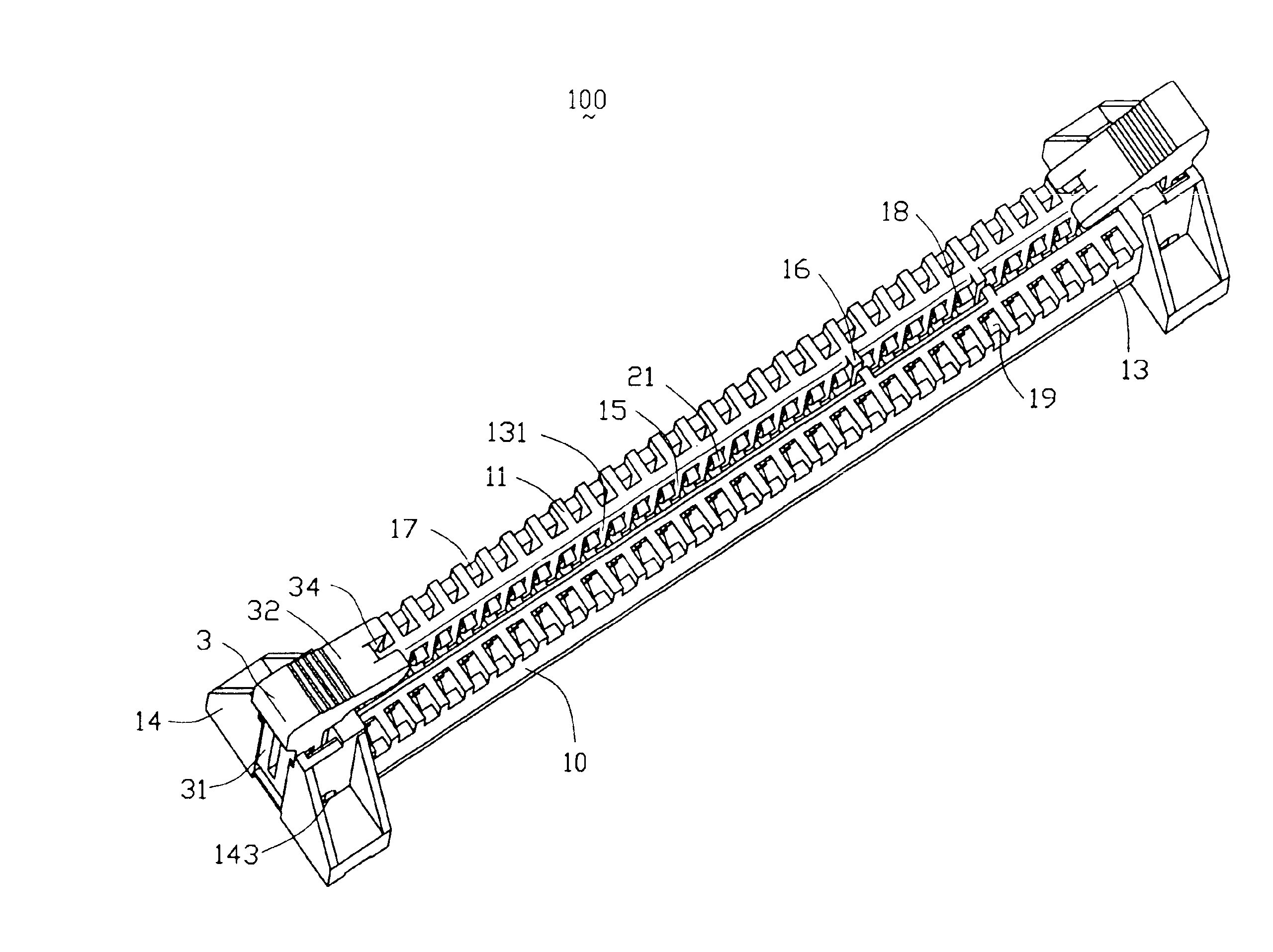
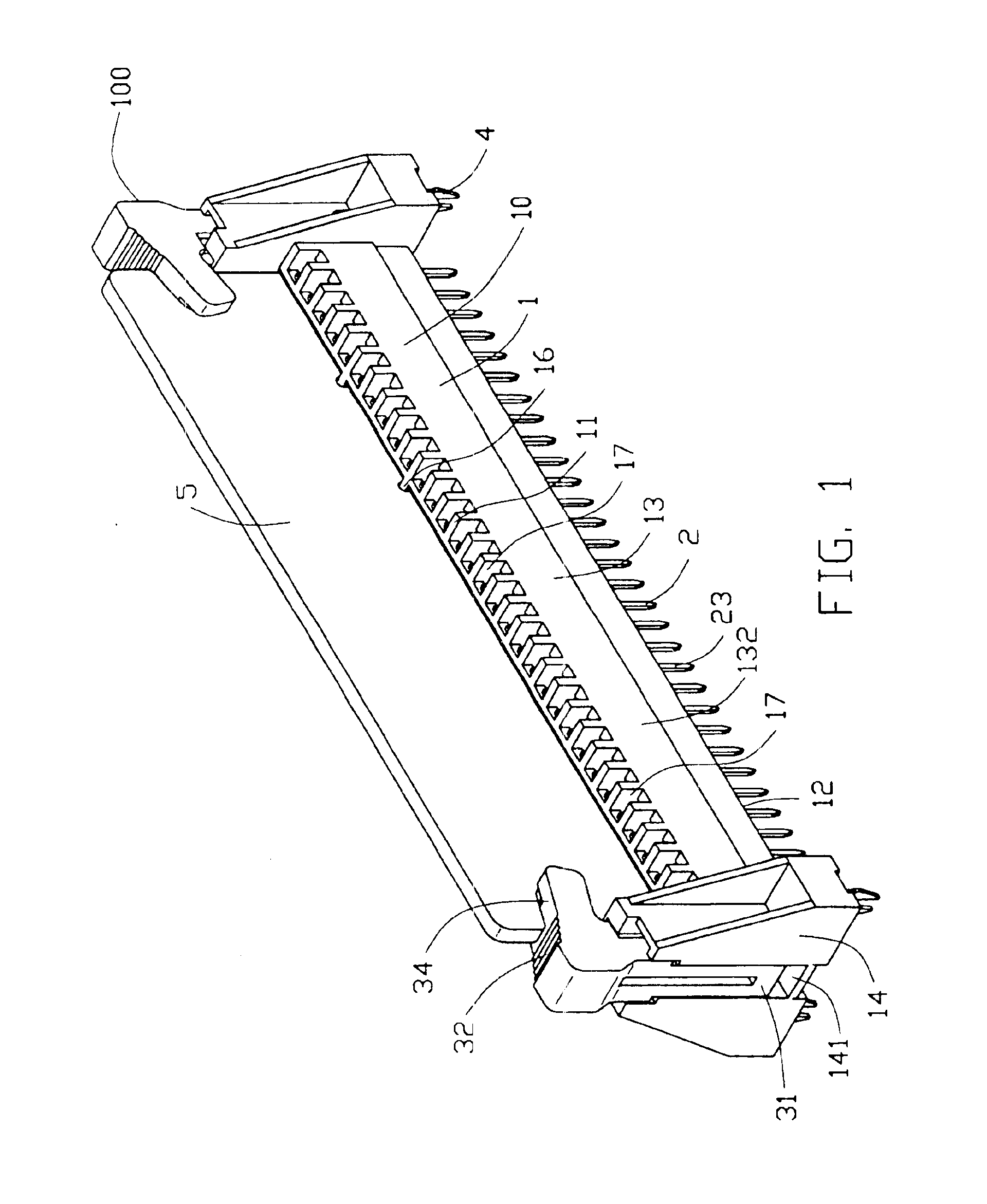
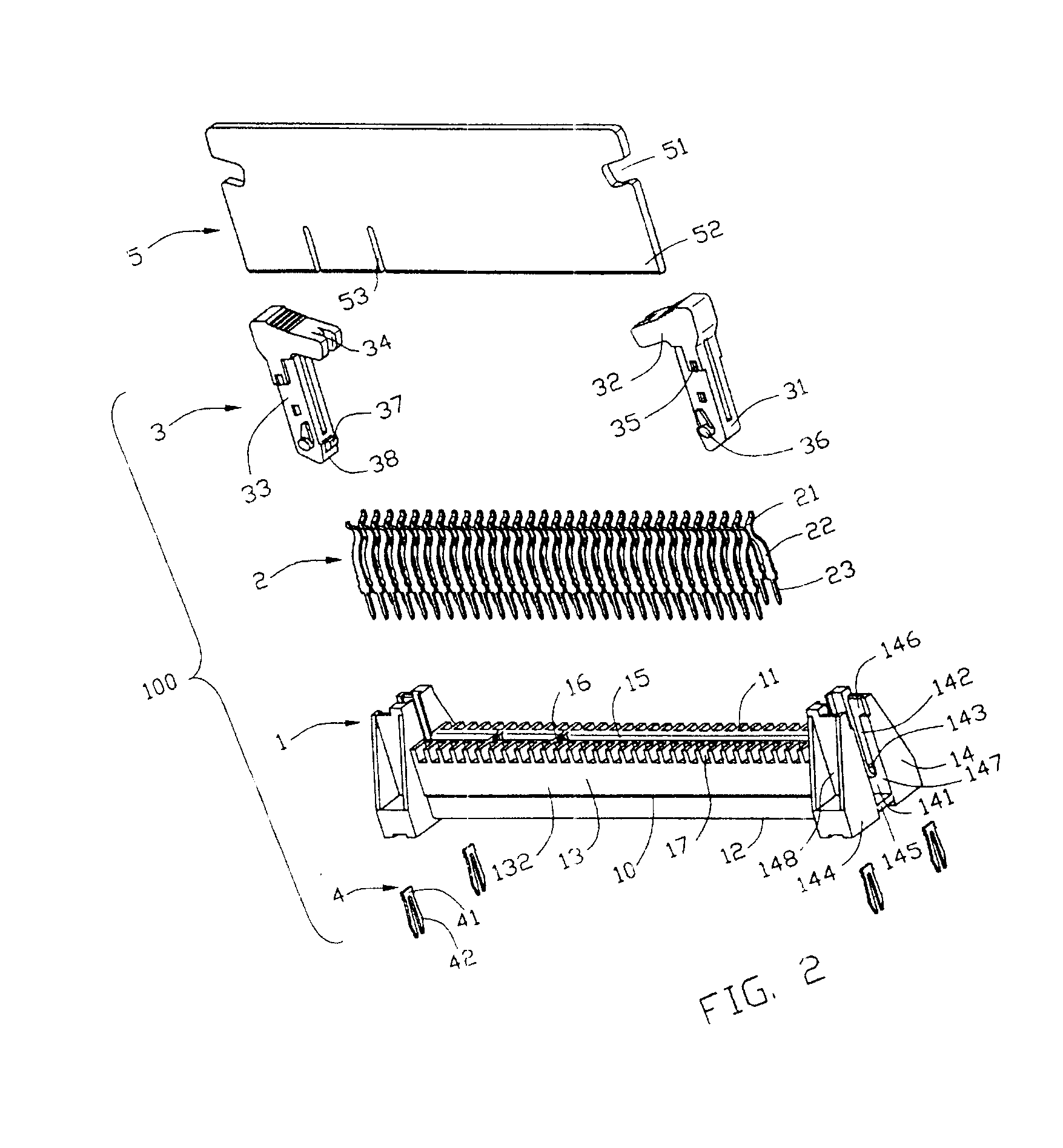
[0013]Referring to FIGS. 1 and 2, an electrical connector 100 in accordance with the present invention is used to mate with an electrical card 5 and comprises an insulative housing 1, a plurality of electrical contacts 2, a pair of latch members 3 and two pairs of retention structures 4.

[0014]The electrical card 5 comprises a pair of cutouts 51 defined on opposite ends thereof, a mating edge 52 on a bottom end thereof and two notches 53 defined in the mating edge 52.

[0015]Further referring to FIGS. 1 and 2 in conjunction with FIG. 3, the insulative housing 1 comprises an elongated base section 10, a pair of mounting sections 14 provided on opposite ends of the base section 10. The base section 10 comprises a pair of elongated side walls 13 and a slot 15 formed between the two side walls 13. Each side wall 13 has a mating face 11, a mounting face 12 opposite to the mating face 11, an inner face 131, and an outer face 132 opposite to the inner face 131. The two side walls 13 are forme...


PUM


Abstract

An electrical connector (100) includes an insulative housing (1) and a number of electrical contacts (2). The insulative housing includes a base (10) having a pair of side walls (13), a slot (15) formed between the two side walls, and a number of passageways (19) and recesses (17) both defined on the side walls. Each side wall has an outer face (132) and each recess extends from a corresponding passageway to the outer face. The electrical contacts are received in the passageways of the insulative housing.

Description

BACKGROUND OF THE INVENTION[0001]1. Field of the Invention[0002]The present invention generally relates to an electrical connector, and more particularly to an electrical connector having a heat-dissipation structure.[0003]2. Description of Related Art[0004]Card edge connectors which electrically connect electrical cards to mother boards within a limited space of a computer or other like electronic device are well known. A conventional card edge connector as shown in U.S. Pat. Nos. 5,059,133, 5,672,069, and 6,210,195 generally includes an insulative housing defining a slot for receiving a mating edge of a complementary electrical card and a plurality of passageways on opposite side walls of the slot and communicating with the slot, and a plurality of contacts received in the passageways. The contacts have mating portions exposed in the slot for contacting with conductive pads on the mating edge of the complementary electrical card and tail portions extending beyond a mounting face o...

Claims


Application Information

Patent Timeline
Patent Type & Authority Patents(United States)
IPC IPC(8): H01R12/18H01R12/30H01R13/00H01R13/629
CPCH01R12/721H01R12/7029H01R12/7058
Inventor ZHAO, QIJUMHU, JINKUIZHANG, GUOHUA
Owner HON HAI PRECISION IND CO LTD
Why Eureka
Try Eureka