
Apparatus for generating vibrations

a technology of apparatus and vibration, applied in the direction of mechanical vibration separation, dynamo-electric machines, supports/enclosements/casings, etc., can solve the problems of mechanical friction and electrical sparks, unbalanced mass of rotating parts, and reducing the lifespan of motors, so as to reduce magnetic force leakage

Inactive Publication Date: 2012-07-26
SAMSUNG ELECTRO MECHANICS CO LTD
View PDF5 Cites 43 Cited by
  • Summary
  • Abstract
  • Description
  • Claims
  • Application Information

AI Technical Summary

Benefits of technology

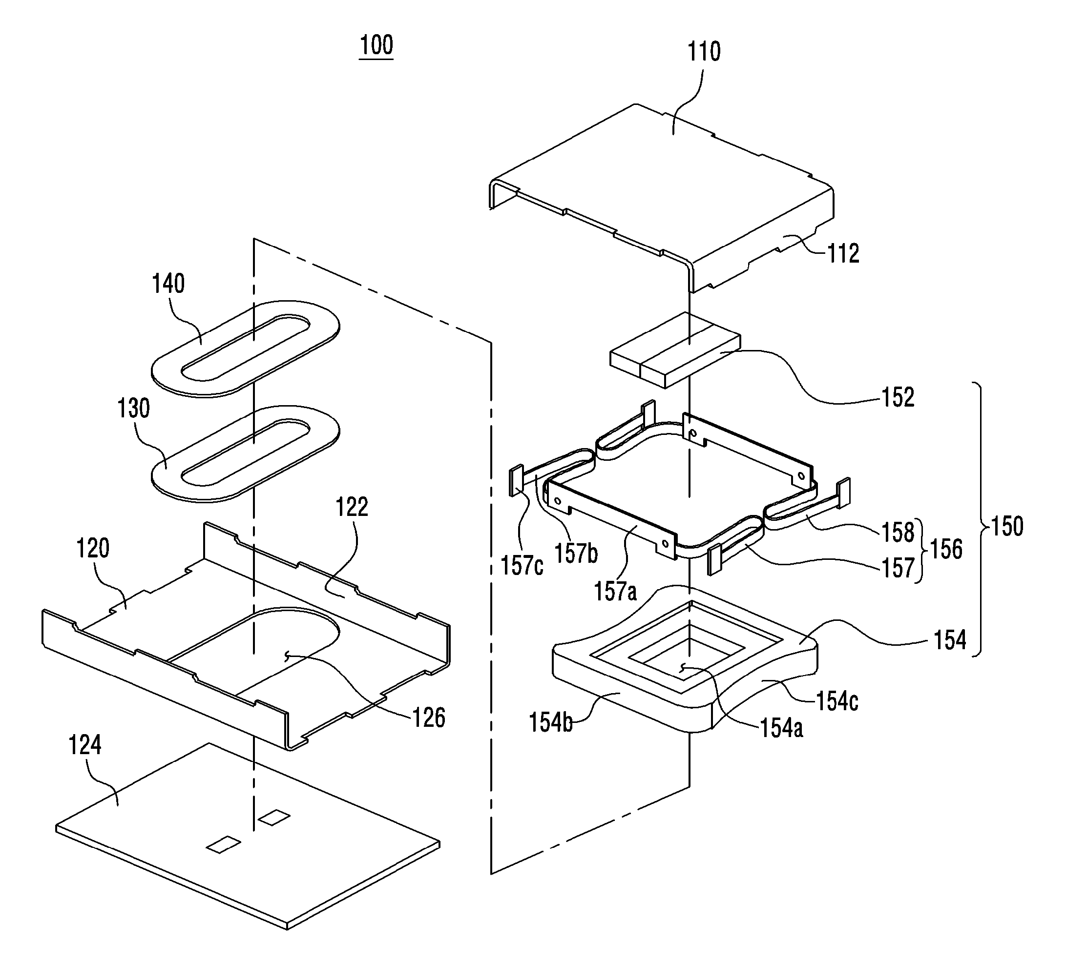
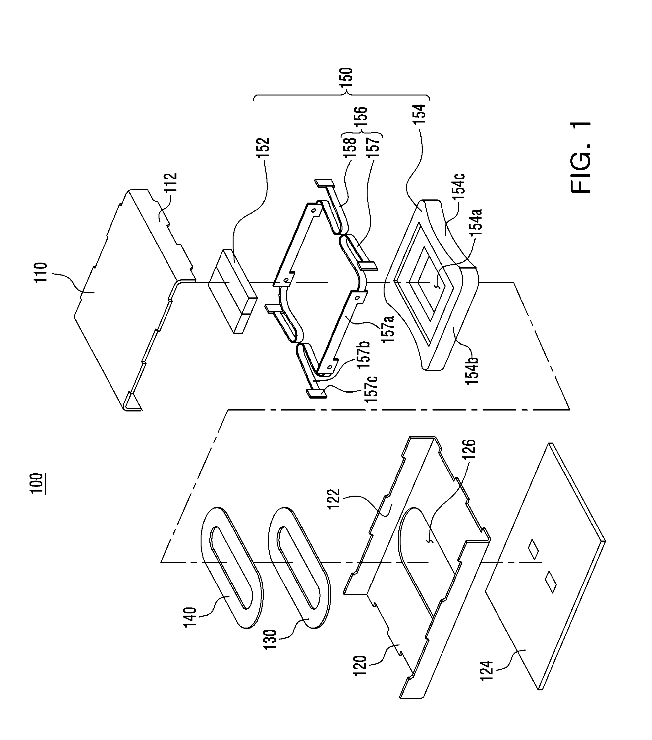
[0014]According to an aspect of the present invention, there is provided an apparatus for generating vibrations, the apparatus including: a lower case made of a non-magnetic material; a coil plate mounted on the lower case and made of a magnetic material so as to reduce magnetic force leakage; a coil mounted on the coil plate; and a motion element including a magnet disposed to be opposite to the coil, such that an electromagnetic force is generated by interaction with the coil.

Problems solved by technology

However, in a vibration motor according to the related art, mechanical friction and electrical sparks may occur during the rotation of a rotating part having an unbalanced mass.
Therefore, abrasion has been generated, and foreign materials have also been generated at the time of spark generation, thereby reducing the lifespan of the motor.
Therefore, it has taken a long time to arrive at target vibrating amount, such that a response speed is slow.
However, in the linear type vibration motor, an attractive force may be generated between a magnet and a case due to a magnetic force generated from the magnet for generating vibrations by electromagnetic interaction with a coil, thereby reducing vibratory strength.

Method used


Image

  • Apparatus for generating vibrations
  • Apparatus for generating vibrations
  • Apparatus for generating vibrations

Examples


Embodiment Construction

[0027]Exemplary embodiments of the present invention will now be described in detail with reference to the accompanying drawings.

[0028]However, it should be noted that the spirit of the present invention is not limited to the embodiments set forth herein and those skilled in the art and understanding the present invention could easily accomplish retrogressive inventions or other embodiments included in the spirit of the present invention by the addition, modification, and removal of components within the same spirit, but those are to be construed as being included in the spirit of the present invention.

[0029]Further, detailed descriptions related to well-known functions or configurations will be ruled out in order not to unnecessarily obscure subject matters of the present invention.

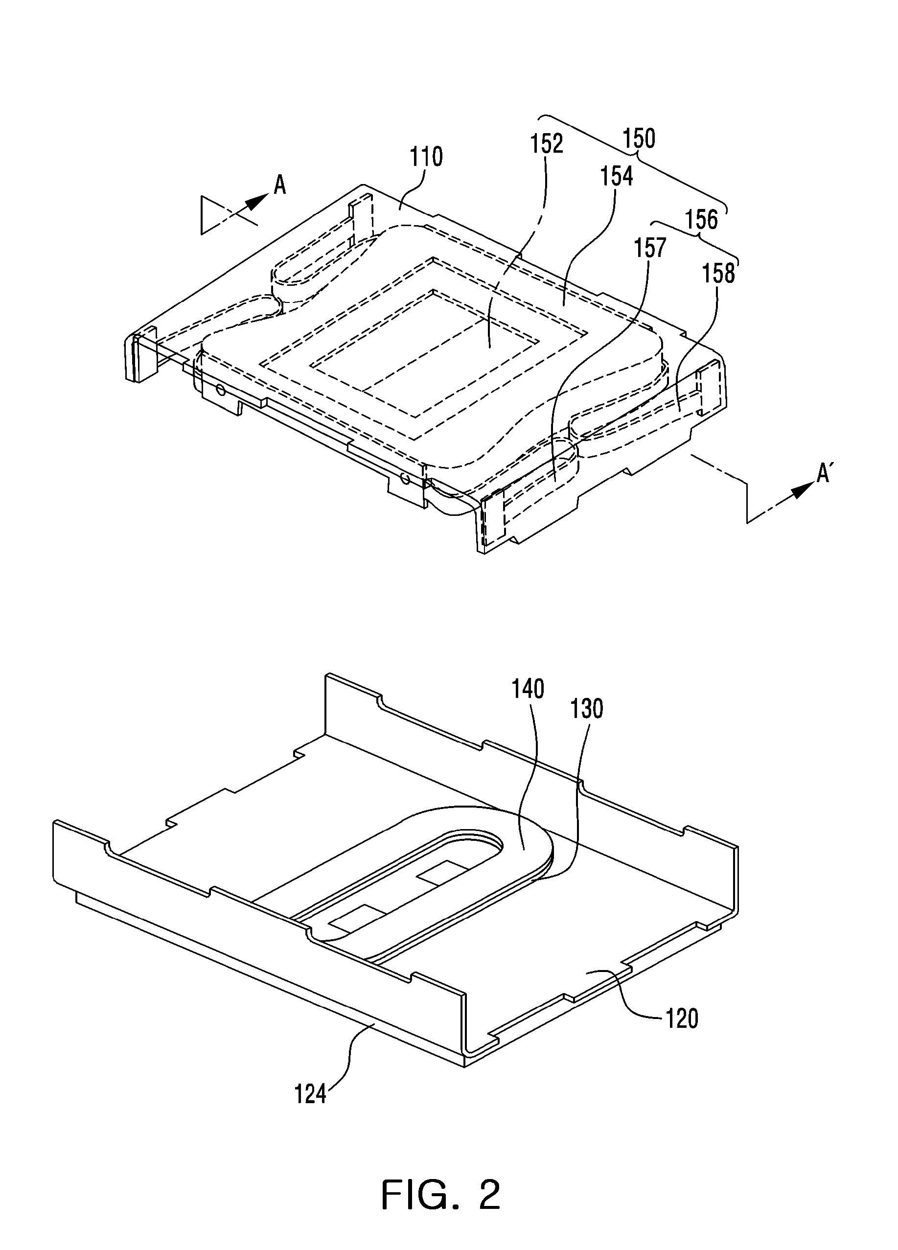
[0030]FIG. 1 is a first exploded perspective view showing an apparatus for generating vibrations according to an exemplary embodiment of the present invention; and FIG. 2 is a second exploded perspective...


PUM


Abstract

There is provided an apparatus for generating vibrations, the apparatus including: a lower case made of a non-magnetic material; a coil plate mounted on the lower case and made of a magnetic material so as to reduce magnetic force leakage; a coil mounted on the coil plate; and a motion element including a magnet disposed to be opposite to the coil such that an electromagnetic force is generated by interaction with the coil.

Description

CROSS-REFERENCE TO RELATED APPLICATIONS[0001]This application claims the priority of Korean Patent Application No. 10-2011-0007272 filed on Jan. 25, 2011, in the Korean Intellectual Property Office, the disclosure of which is incorporated herein by reference.BACKGROUND OF THE INVENTION[0002]1. Field of the Invention[0003]The present invention relates to an apparatus for generating vibrations, and more particularly, to an apparatus for generating vibrations through electromagnetic force.[0004]2. Description of the Related Art[0005]A vibration motor, a component converting electrical energy into mechanical vibrations using the principle of generating an electromagnetic force, is mounted in a mobile phone to be used for silently notifying a user of call reception by transferring vibrations thereto.[0006]In accordance with the rapid growth in the market for mobile phones and the trend of multi-functionality in mobile phone, mobile phone components having a compact size and a high qualit...

Claims


Application Information

Patent Timeline
IPC IPC(8): H02K33/00
CPCH02K33/16B06B1/04H02K5/02H02K33/02
Inventor BANG, JE HYUNPARK, SUCK JUNCHOI, JUN KUNKIM, YONG JIN
Owner SAMSUNG ELECTRO MECHANICS CO LTD
Learn More