
Adjustment mechanism for rotation runout and dynamic balance of rotating tool

a technology of rotating tool and adjustment mechanism, which is applied in the direction of mechanical equipment, manufacturing tools, electric programme control, etc., can solve the problems of time-consuming operation, significant unbalance, and damage to bearings

Active Publication Date: 2015-07-23
FANUC LTD
View PDF12 Cites 10 Cited by
  • Summary
  • Abstract
  • Description
  • Claims
  • Application Information

AI Technical Summary

Benefits of technology

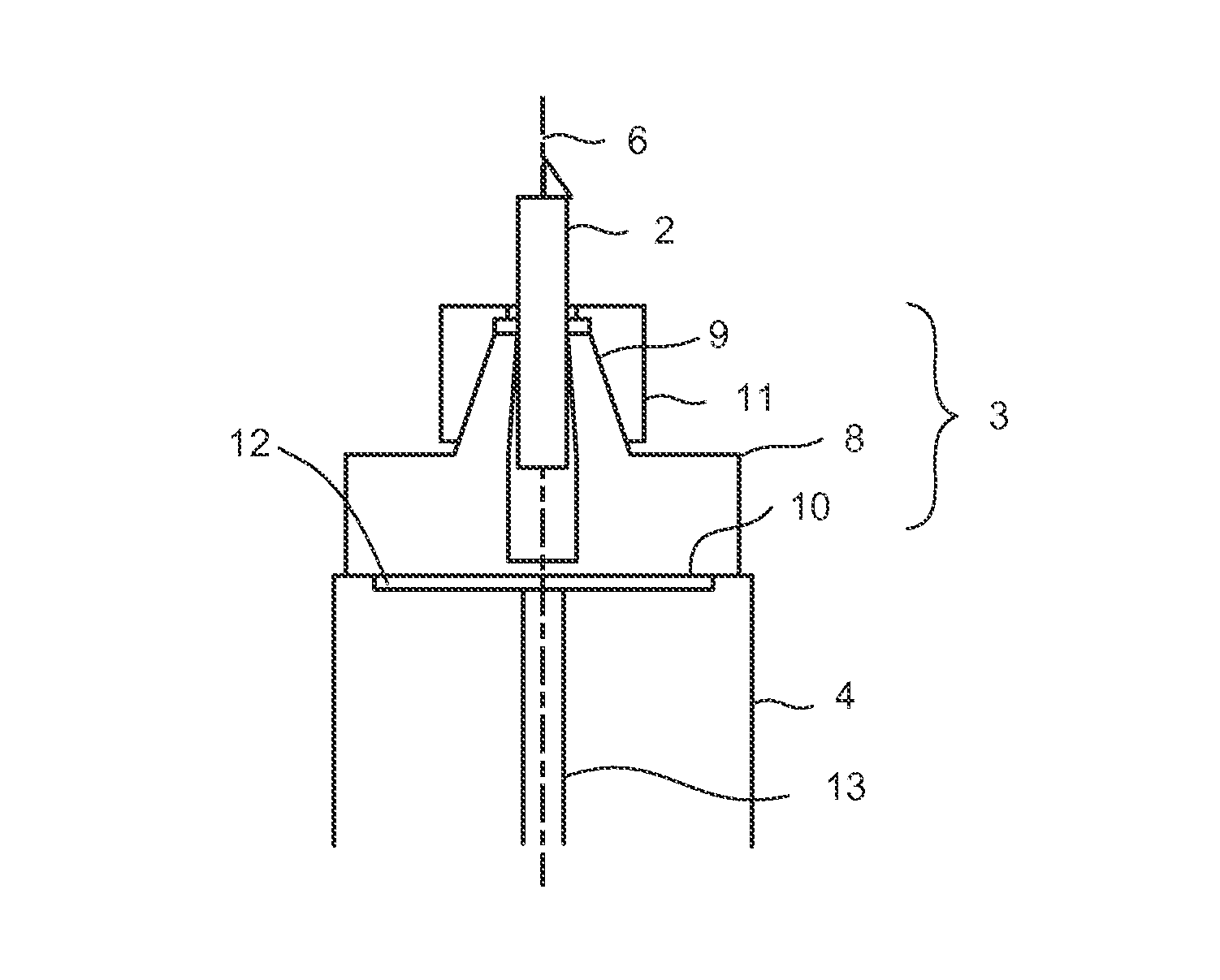
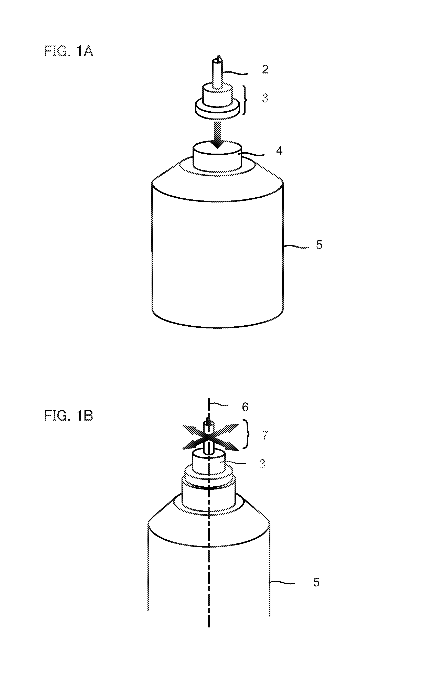
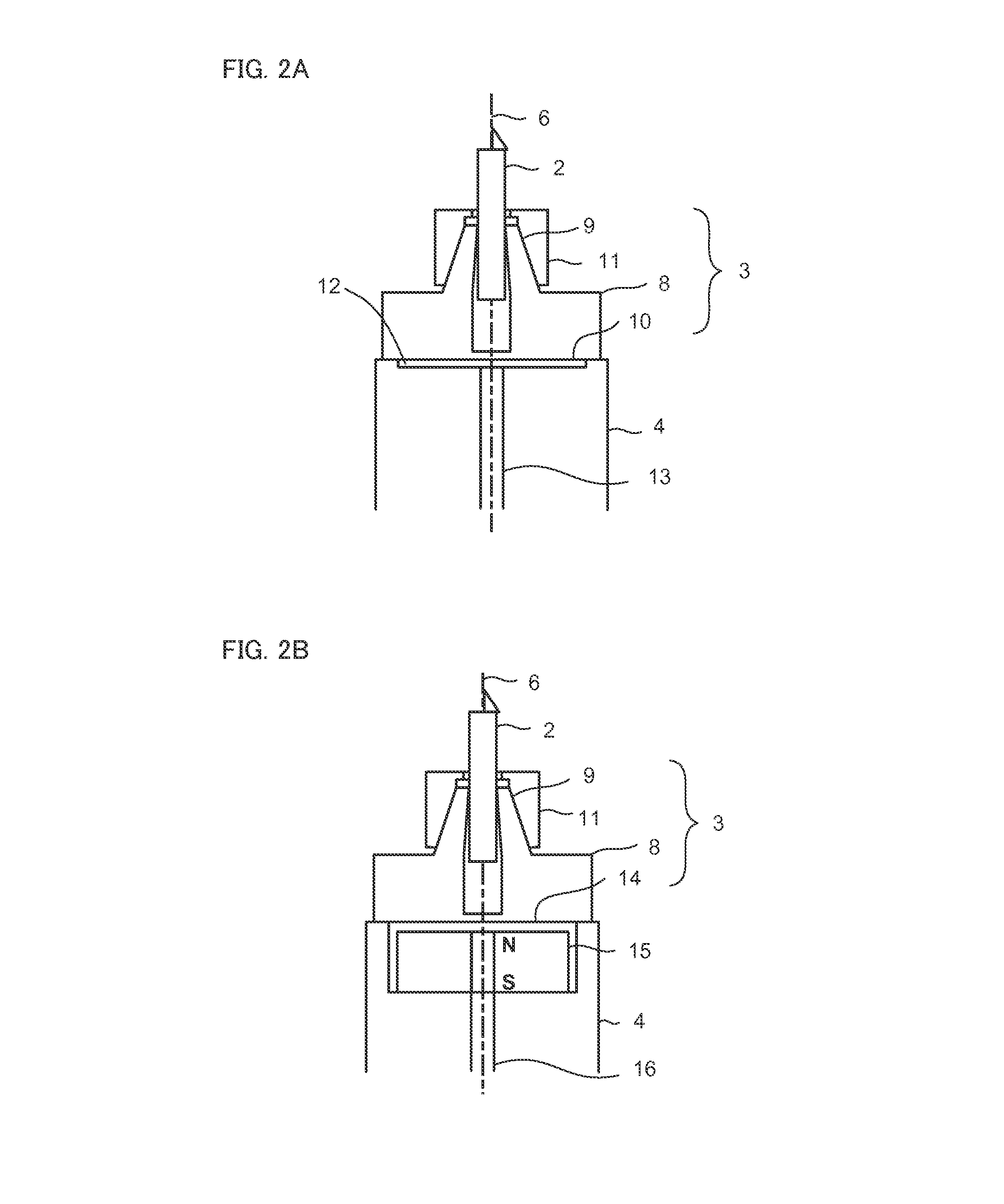
The present invention is a tool holder that can be attached to a spindle using a vacuum chuck or magnetic chuck. The tool holder has projections along its outer edge that come into contact with a stationary section when the spindle is rotated. This allows for easy adjustment of the tool holder's position in any direction. The invention also provides an adjustment mechanism to address rotation runout and dynamic balance issues of the rotating tool. This means that the spindle shaft can be rotated while keeping the tool holder in place, thus enabling easy adjustment of the rotating tool's rotation.

Problems solved by technology

The air bearing offers only low resistance to a heavy load, and thus, the bearing may be damaged when the spindle shaft is rotated at high speed with significant unbalance present.
This is a time-consuming operation.
Thus, during the correction, the rotation of the spindle inevitably needs to be stopped.
The collet chuck and the shrinkage fitting chuck have structures unlikely to be displaced at the time of attachment but are not configured to be able to correct displacement.
Furthermore, in the structures of these chucks, it is difficult to limit the positional displacement in the direction orthogonal to the rotational axis to 1 μm or less and to limit the deviation of the dynamic balance during rotation to 10 mg or less.
The attachment of a weight for balance allows the dynamic balance to be manually adjusted but leads to the need to stop rotation of the spindle shaft each time the weight is attached.
Automating the attachment and detachment of the weight is also difficult.

Method used


Image

  • Adjustment mechanism for rotation runout and dynamic balance of rotating tool
  • Adjustment mechanism for rotation runout and dynamic balance of rotating tool
  • Adjustment mechanism for rotation runout and dynamic balance of rotating tool

Examples


first embodiment

[0066]First, the adjustment mechanism for rotation runout and dynamic balance of the rotating tool according to the present invention will be described using FIG. 3.

[0067]The tool holder 3 includes a first projection 19 on an outer peripheral surface thereof at a predetermined position. A fixing member 20 includes a second projection 21. The second projection 21 is disposed on a plane formed by the trajectory of the first projection 19 when the spindle shaft 4 is rotated. The spindle 5 is attached to a slide 17 that moves up and down to enable a change in a relative distance La between the first projection 19 and the second projection 21. Moving the slide 17 in a slide moving direction depicted in FIG. 3 enables the first projection 19 to collide against the second projection 21. The height by which the first projection 19 projects from a peripheral surface of the tool holder 3 is set larger than the amount of decentering of the tool holder 3 from the rotational axis 6 (the normally...

second embodiment

[0074]Now, the adjustment mechanism for rotation runout and dynamic balance of the rotating tool will be described using FIG. 6A and FIG. 6B.

[0075]As depicted in FIG. 6A, four first projections (19a, 19b, 19c and 19d) are disposed on the outer peripheral surface of the tool holder 3 so as to have phases different from one another by 90° with respect to the center of rotation 28. The four first projections 19a, 19b, 19c and 19d are disposed at different positions in the direction 30 of the rotational axis as depicted in FIG. 6B corresponding to FIG. 6A as viewed in the direction of arrow 29. Thus, planes formed by the trajectory of the first projection 19a, 19b, 19c and 19d during rotation avoid overlapping one another. When the spindle 5 is moved in an “approaching direction 31” depicted in FIG. 6B with the spindle shaft 4 of the spindle 5 kept rotating, only one of the first projections 19a, 19b, 19c and 19d, that is, the projection 19a, collides against the second projection 21, w...

third embodiment

[0077]Now, the adjustment mechanism for rotation runout and dynamic balance of the rotating tool according to the present invention will be described using FIG. 7.

[0078]A machine tool M as a whole is controlled by a numerical controller 40. The machine tool M includes, on a machine base 41, an X axis base 42 that supports an X axis slide 43 so that the X axis slide 43 is movable and a Y axis base 44 that supports a Y axis slide 45 so that the Y axis slide 45 is movable. A workpiece 33 is placed on the X axis slide 43. A Z axis base 46 is fixed to the Y axis slide 45; the Z axis base 46 supports a Z axis slide 47 so that the Z axis slide 47 is movable. The spindle 5 chucking the tool holder 3 is attached to the Z axis slide 47. The second projection 21 is provided on a fixing member 20 (see FIG. 6A) attached to the machine base 41. Reference numeral 50 denotes a power and signal line.

[0079]The dispositions of the first projection 19 and the second projection 21 are similar to the dis...


PUM


Abstract

A tool holder holding a rotating tool can be sucked in a direction of a rotational axis of a spindle and a direction perpendicular to the direction of the rotational axis, using a chuck. A projection is provided on an outer peripheral surface of the tool holder, and caused to collide against another projection with the spindle kept rotating, to displace the tool holder. Thus, runout and dynamic balance of the rotating tool are adjusted.

Description

BACKGROUND OF THE INVENTION[0001]1. Field of the Invention[0002]The present invention relates to an adjustment mechanism for rotation runout and dynamic balance of a rotating tool.[0003]2. Description of the Related Art[0004]A spindle includes a spindle shaft to which a rotating tool is attached. In a machine tool, the rotating tool is generally attached to the spindle shaft using a collet chuck or a shrinkage fitting chuck. These chuck structures are subjected to little positional displacement, and the chucks have sufficient strengths.[0005]In particular, spindles used for ultra-precision machining use an air bearing in order to reduce heat from and vibration in the bearing of the spindle shaft. The air bearing offers only low resistance to a heavy load, and thus, the bearing may be damaged when the spindle shaft is rotated at high speed with significant unbalance present. Thus, each time the balance is corrected, the rotation speed of the spindle shaft needs to be increased. The a...

Claims


Application Information

Patent Timeline
IPC IPC(8): B23Q11/00B23Q17/22G05B19/19B23Q15/22
CPCB23Q11/0035G05B19/19B23Q17/2216B23Q15/22B23Q2017/001Y10T279/11Y10T279/21
Inventor EBIHARA, KENZO
Owner FANUC LTD
Learn More