Spring-effect pushbutton

a pushbutton and spring technology, applied in the field of spring-effect pushbutton, can solve the problems of increasing the cost of the pump, affecting the appearance, and affecting the appearance, and achieve the effect of convenient manufacturing

Inactive Publication Date: 2001-12-27
LOREAL SA
View PDF0 Cites 22 Cited by
  • Summary
  • Abstract
  • Description
  • Claims
  • Application Information

AI Technical Summary

Benefits of technology

0012] The pushbutton of the invention makes it possible to avoid using a metal spring for returning the pump to its initial configuration after dispensing a quantity of fluid, and to do so without presenting the above-mentioned drawbacks of U.S. Pat. No. 5,363,9

Problems solved by technology

Nevertheless, the use of such a metal spring increases the cost price of the pump and can give rise to problems of corrosion and compatibility with the fluid dispensed.
Su

Method used


Image

  • Spring-effect pushbutton
  • Spring-effect pushbutton
  • Spring-effect pushbutton

Examples


Embodiment Construction

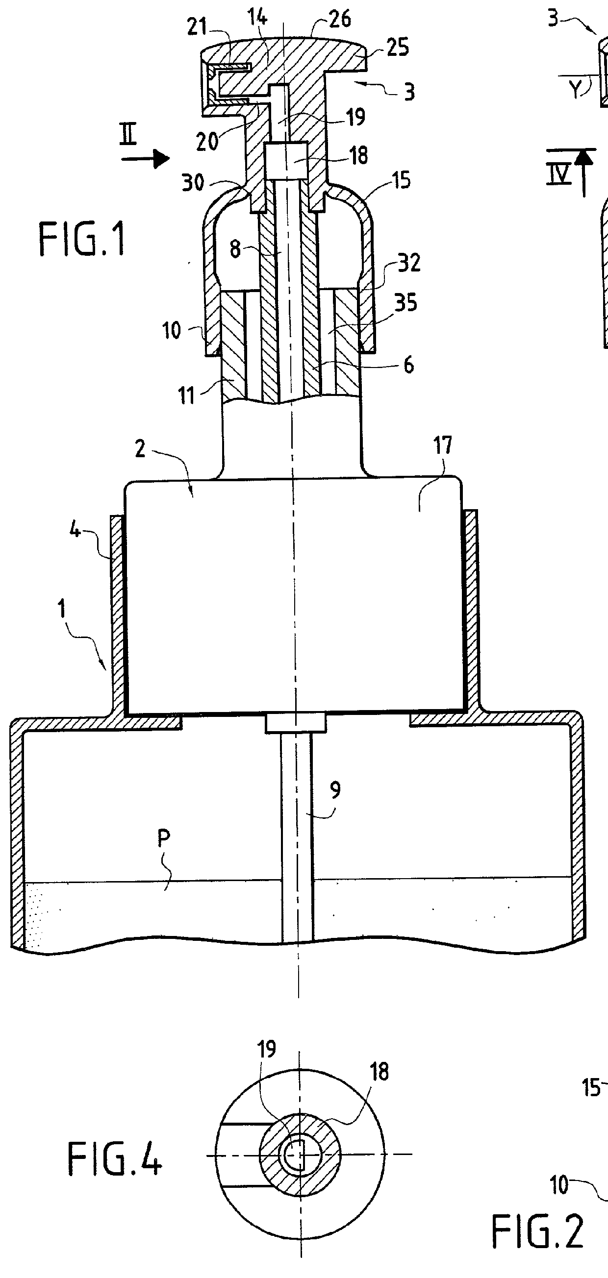
[0042] FIG. 1 is a fragmentary and highly diagrammatic view of a conventional receptacle 1 provided with a pump 2 fitted with a pushbutton 3 of the invention.

[0043] The receptacle 1 is filled with a liquid or semi-liquid fluid P that comes into contact with the body of the receptacle itself in the example described.

[0044] In a variant that is not shown the fluid P could be contained in a bag that is capable of collapsing as the fluid is dispensed.

[0045] The pump 2 can allow or prevent ingress of air.

[0046] The pump comprises a pump body 17 and a hollow rod 6 that is movable in translation along the axis X relative to the pump body 17 so as to move downwardly in order to dispense a quantity of fluid.

[0047] The pump body 17 is secured in an assembly skirt 4 formed at the top of the receptacle 1 and it houses, in conventional manner, a suction valve and a delivery valve (not shown in the drawing), co-operating with a piston that is also not shown in the drawing and that is secured to t...


PUM


Abstract

A pushbutton for actuating a dispenser member, the dispenser member having a moving element that is movable between two positions, the pushbutton having a base, a head defining both a bearing surface for a user and a dispensing orifice, and an elastically-deformable portion interconnecting the base and the head, the head being suitable for being secured to the moving element. The elastically-deformable portion is arranged so as to deform in the sense of rolling onto itself when the head is depressed and is suitable for returning the moving element into an initial position by resilient return.

Description

[0001] The present invention relates to the field of devices for packaging and dispensing a liquid or semi-liquid fluid, in particular a cosmetic.[0002] The invention relates more particularly to devices including a manually-actuated pump for dispensing a quantity of fluid.[0003] In conventional manner, such pumps comprise a pushbutton defining a bearing surface for the user that is mounted at the top end of a hollow control rod for the pump and that is to be depressed at the time of use.[0004] It is known to use a metal spring to return the pushbutton to its initial position after dispensing a quantity of fluid.[0005] Nevertheless, the use of such a metal spring increases the cost price of the pump and can give rise to problems of corrosion and compatibility with the fluid dispensed.[0006] U.S. Pat. No. 5,363,993 proposes a pump in which the pushbutton is secured to a spring-forming bellows, enabling it to be returned to its initial position after dispensing a quantity of fluid.[00...

Claims


Application Information

Patent Timeline
IPC IPC(8): A45D34/04B05B11/00B65D83/16B65D83/76F04B9/14F04B53/00
CPCB05B11/3042B05B11/3074B05B11/3077B65D83/20B05B11/1042B05B11/1074B05B11/1077
Inventor BETHUNE, ALAINROUSSELET, GUILHEM
Owner LOREAL SA
Why Eureka
Try Eureka