Electromagnetic valve

a technology of electromagnetic valve and plunger, which is applied in the direction of valve details, valve arrangement, machines/engines, etc., can solve the problems of increased cost, increased oil leakage through the clearance between the large diameter portion and the sleeve, and deterioration of magnetic efficiency, so as to reduce the size of the generating magnetic force, improve the magnetic efficiency of the air gap, and improve the effect of magnetic efficiency

Inactive Publication Date: 2006-10-03
DENSO CORP
View PDF3 Cites 9 Cited by
  • Summary
  • Abstract
  • Description
  • Claims
  • Application Information

AI Technical Summary

Benefits of technology

[0012]It is therefore an object of the present invention to provide an electromagnetic valve capable of preventing deformation of a plunger and a valve member such as a spool even though a shaft is press-fit into at least one of the plunger and the valve member.
[0014]Therefore, in the case where the shaft is press-fit into a plunger, deformation due to the press-fitting process is absorbed by the diameter reduction of the shaft. Accordingly, deformation of the plunger can be inhibited. Thus, it is unnecessary to give a large margin to an air gap around the plunger and a magnetic efficiency at the air gap can be improved. As a result, a magnetic force applied to the plunger is increased, and a coil for generating the magnetic force can be reduced in size.
[0015]In the case where the shaft is press-fit into a valve member, deformation due to the press-fitting process is absorbed by the reduction of the diameter of the shaft. Thus, the deformation of the valve member can be inhibited. For instance, in the case where the shaft is press-fit into a spool, the deformation caused by press-fitting the shaft is absorbed by the reduction of the diameter of the shaft. Accordingly, deformation of the spool is inhibited and a problem of transmission of the deformation of the spool to a large diameter portion (land) of the spool can be prevented. Thus, it is unnecessary to give a large margin to a clearance between the large diameter portion and the sleeve, and a quantity of oil leaking through the clearance between the large diameter portion and the sleeve can be suppressed.

Problems solved by technology

A quantity of oil leaking through the clearance between the large diameter portion and the sleeve will increase if the clearance has a large margin.
However, a magnetic resistance is enlarged at the helical groove, so the magnetic efficiency will be deteriorated.
In addition, the helical groove on the outer peripheral surface requires a complicated manufacturing process, so the cost will be increased.

Method used


Image

  • Electromagnetic valve
  • Electromagnetic valve
  • Electromagnetic valve

Examples


Embodiment Construction

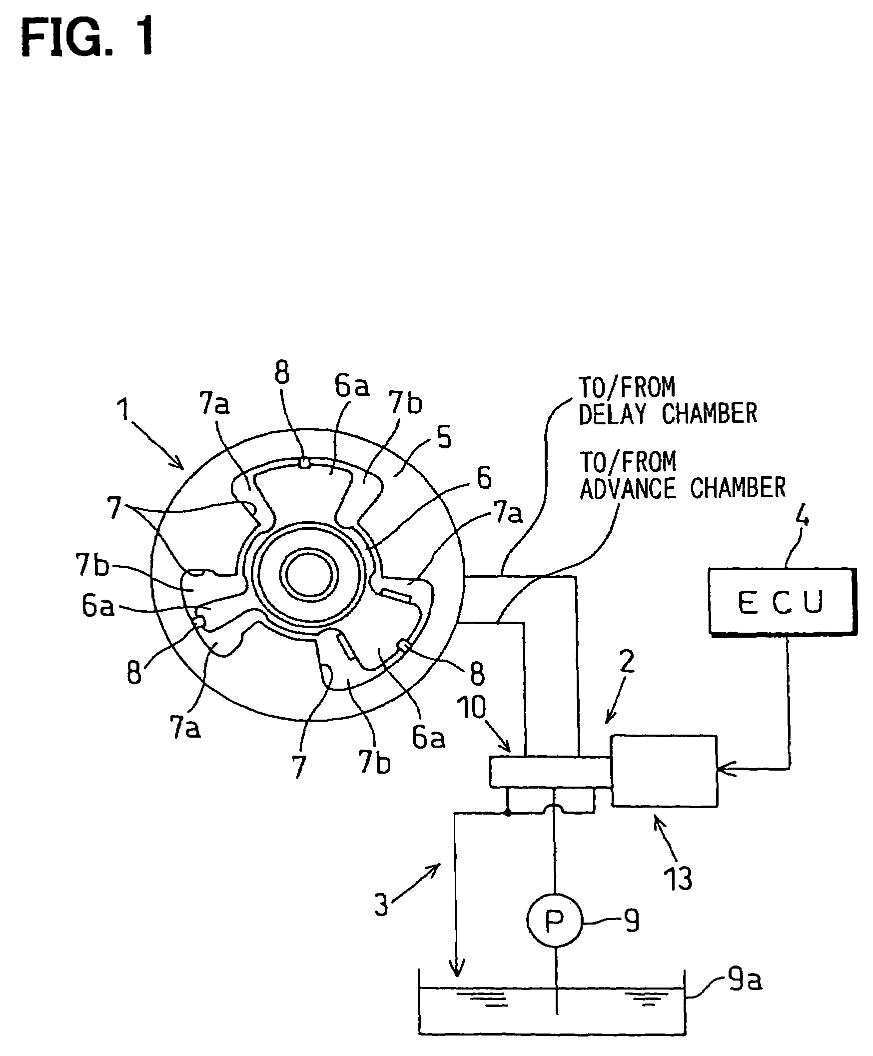
[0022]Referring to FIG. 1, a variable valve timing device (VVT) according to a first example embodiment of the present invention is illustrated.

[0023]The VVT shown in FIG. 1 is attached to a camshaft (either one of an intake valve camshaft, an exhaust valve camshaft and an intake-exhaust valve camshaft) of an internal combustion engine. The VVT can continuously vary opening-closing timing of a valve.

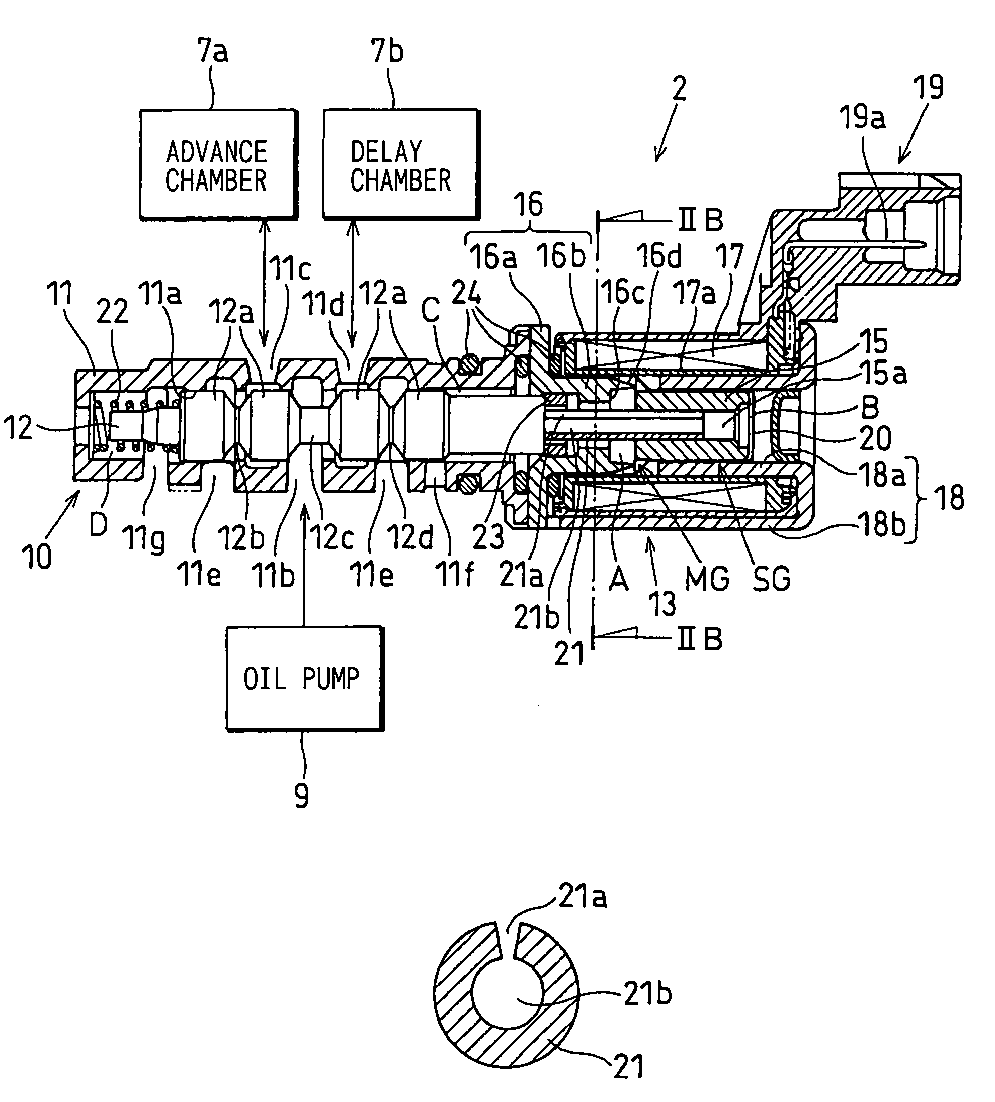
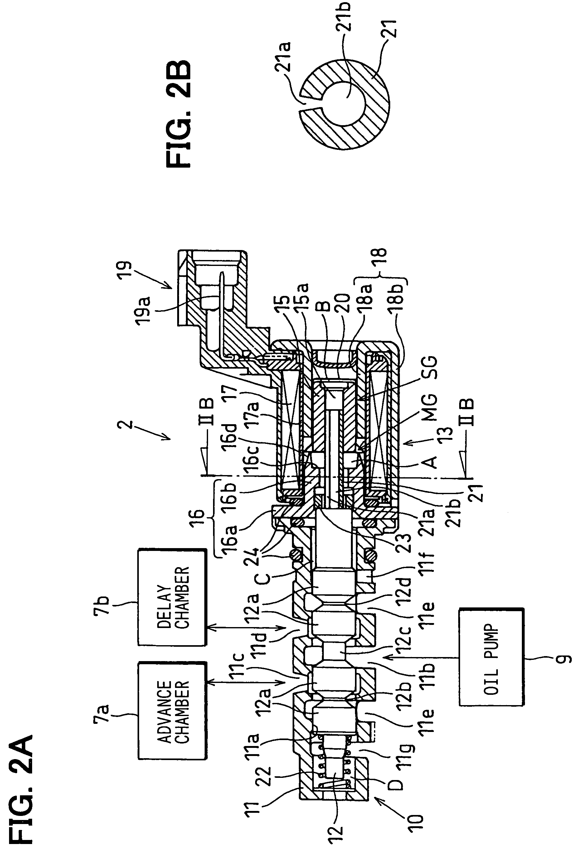
[0024]The VVT includes a variable cam timing mechanism (VCT) 1, an oil pressure circuit 3 including an oil flow control valve (OCV) 2, and an electronic control unit (ECU) 4 for controlling the OCV 2.

[0025]The VCT 1 includes a shoe housing (rotary driving member) 5 and a vane rotor (rotary driven member) 6. The shoe housing 5 is driven to rotate in synchronization with a crankshaft of the engine. The vane rotor 6 is provided to rotate relative to the shoe housing 5 and to rotate together with the camshaft. An oil pressure actuator provided in the shoe housing 5 drives and rotates the van...


PUM


Abstract

A shaft is press-fit into the valve member or the plunger of an electromagnetic valve to transmit the axial movement of the plunger to the valve member. A diameter reducing mechanism is provided for reducing the diameter of at least the press-fit portion of the shaft so that the diameter of the shaft is decreased by a press-fitting force applied to the shaft by the valve member and / or plunger. Deformation due to the press-fitting process is absorbed by the shaft, so deformation of the valve member and / or plunger is inhibited. Accordingly, it is unnecessary to give a large margin to a plunger side air gap, and magnetic efficiency can be improved. Also, two chambers on both axial sides of the plunger can communicate with each other through a clearance provided by the C-shaped cross-section, an inner hole and a penetration hole of the shaft. Therefore, it is unnecessary to form any separate groove or hole in the plunger for respiration.

Description

CROSS REFERENCE TO RELATED APPLICATION[0001]This application is based on and incorporates herein by reference Japanese Patent Application No. 2004-194254 filed on Jun. 30, 2004.BACKGROUND OF THE INVENTION[0002]1. Field of the Invention[0003]The present invention relates to an electromagnetic valve that drives a valve device by operating an electromagnetic actuator. Specifically, the present invention relates to a technology suitably applicable to an oil flow control valve (OCV) that alters a flow of oil by operating the electromagnetic actuator.[0004]2. Description of Related Art[0005]An oil flow control valve (OCV) is an oil pressure control valve having a spool valve (valve device) and an electromagnetic actuator. The OCV operates the electromagnetic actuator to displace a plunger in an axial direction against a biasing force of a return spring. The OCV transmits the displacement of the plunger to a spool (valve member) to displace the spool in the axial direction. Thus, the OCV s...

Claims


Application Information

Patent Timeline
Patent Type & Authority Patents(United States)
IPC IPC(8): F01L1/34
CPCF16K31/0613F01L2001/3443F01L2001/34433
Inventor KONDO, JIRO
Owner DENSO CORP
Why Eureka
Try Eureka